MMK
1 /14Pages

MMK
1 /14Pages
Catalog excerpts

Latching Relay Mechanically Latching Relays Based on the MM Power Relay • Low power consumption due to mechanical latch for economic operation. • Relays with mixed coil specifications can be produced (e.g., AC set coil and DC reset coil). • Operational response fast enough to enable pulse signal power applications. • Ambient operating temperature: –10°C to 55°C. Refer to Safety Precautions for All Relays. Ordering Information Type Contact form Open structure Solder terminals Screw terminals Plug-in (octal pins) terminals Conforming to auxiliary power DPDT+DPST-NO relay specifications Models Conforming to Auxiliary Power Relay Specifications The MM4KP-JD and MM4XKP-JD satisfy the ratings of auxiliary relays provided in JEC-2500 (1987) standards for power protective relays specified by the Japan Electromechanical Commission. Furthermore, the MM4KP-JD and MM4XKP-JD satisfy the ratings of multi-contact relays provided in JEC-174D (1979) standards for power auxiliary relays. These models work at operation level A specified by JEC-174D (1979) standards and the hot start of the relays is possible after the coils radiate heat. In accordance with JEC-2500 (1987) standards, the coil of each model withstands a 130% DC load or 115% AC load. Note: When ordering, add the rated coil voltage to the model number. Rated coil voltages are given in the coil ratings table. Example: MM2K, 6 VAC Rated coil voltage ■ Available Models Open Coils (with Solder Terminals) Type Standard Contact form Relay model Available rated voltage
Open the catalog to page 1
MMK Open Coils (with Screw Terminals) Type Standard Contact form Relay model Available rated voltage Cased Coils (Plug-in Terminals) Type Standard Contact form Relay model Available rated voltage Conforming to auxiliary power relay specifications Conforming to auxiliary power relay specifications for DC-switching Model Number Legend MM@@K@ 1 1. Contact Form 2: DPDT 3: 3PDT 4: 4PDT (open structure type)/ DPDT+DPST-NO (cased type) 2. Type (see note) None: Standard X: DC-switching 3. Terminal Shape None: Solder B: Screw P: Plug-in Note: The suffix “JD” indicates models conforming to auxiliary power...
Open the catalog to page 2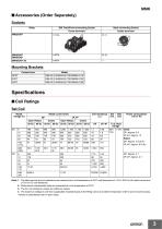
■ Accessories (Order Separately) Sockets Relay Back-connecting Socket Screw terminals Solder terminals Mounting Brackets Contact form Specifications ■ Coil Ratings Set Coil Rated voltage (V) Rated current (mA) DP Open Relays 50 Hz Open Relays Note: 1. The rated current and coil resistance are measured at a coil temperature of 23°C with tolerances of +15%/–20% for AC rated current and ±15% for DC coil resistance. 2. Performance characteristic data are measured at a coil temperature of 23°C. 3. The AC coil resistance values are reference values. 4. The maximum voltage is one that is applicable...
Open the catalog to page 3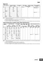
MMK Reset Coil Rated voltage (V) Maximum voltage Initial: Approx. 6.5 Rated: Approx. 4.1 Reset voltage Note: 1. The rated current and coil resistance are measured at a coil temperature of 23°C with tolerances of +15%/–20% for AC rated current and ±15% for DC coil resistance. 2. Performance characteristic data are measured at a coil temperature of 23°C. 3. The AC coil resistance values are reference values. 4. The maximum voltage is one that is applicable instantaneously to the Relay coil at an ambient temperature of 23°C and not continuously. Coils (Conforming to Auxiliary Power Relay Specifications)...
Open the catalog to page 4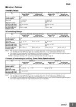
■ Contact Ratings Standard Relays Item Open Relays: MM2K(B), MM3K(B), MM4K(B) Resistive load (cosφ = 1) Resistive load (cosφ = 1) Contact mechanism Contact material Rated load Rated carry current Max. switching power (reference value) DC-switching Relays Item Open Relays: MM2XK(B), MM3XK(B), MM4XK(B) Resistive load (cosφ = 1) Contact mechanism Resistive load (cosφ = 1) Contact material Rated load Rated current flow Max. switching power (reference value) Note: 1. When switching DC inductive loads at 125 V or more, an unstable region exists for a switching current of between 0.5 and 2.5 A. The...
Open the catalog to page 5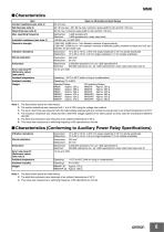
Open or bifurcated-contact Relays Contact resistance (see note 2) AC: 30 ms max.; DC: 60 ms max. (minimum pulse width for AC and DC: 100 ms) Reset time (see note 3) 30 ms max. (minimum pulse width for AC and DC: 100 ms) Mechanical: Electrical: Insulation resistance (see note 4) Dielectric strength 1,500 VAC, 50/60 Hz for 1 min between contacts of same polarity 2,000 VAC, 50/60 Hz for 1 min between contacts of different polarity, between contacts and coil, and between set and reset coils Vibration resistance Destruction: Malfunction: 10 to 55 to 10 Hz, 0.375 mm single amplitude (0.75 mm double...
Open the catalog to page 6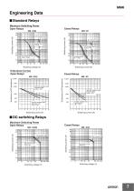
Engineering Data ■ Standard Relays Maximum Switching Power Open Relays Cased Relays AC inductive load (cosφ = 0.4) DC resistive load AC inductive load (cosφ = 0.4) Endurance Curves Open Relays Cased Relays 220 VAC resistive load Inductive load (cosφ = 0.4) 24 VDC resistive load Inductive load L/R = 7 ms MM@KP Endurance (x10 3 operations) 220 VAC resistive load Inductive load (cosφ = 0.4) 24 VDC resistive load Inductive load L/R = 7 ms ■ DC-switching Relays Maximum Switching Power Open Relays Cased Relays
Open the catalog to page 7
MMK Endurance Curves Open Relays Cased Relays MM@XKP 10,000 5,000 3,000 110 VDC resistive load 1,000 500 110 VDC inductive load (L/R 7 ms) 110 VDC resistive load Inductive load L/R=7 ms ■ Relays Conforming to Auxiliary Power Relay Specifications Maximum Switching Power MMX4KP-JD AC inductive load cosφ = 0.4 AC resistive load Switching current (A) 220 VAC resistive load Inductive load cosφ = 0.4 110 VDC resistive load Inductive load L/R = 7 ms 24 VDC resistive load Inductive load L/R = 7 ms
Open the catalog to page 8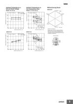
Set voltage Reset voltage Coil temperature rise (° C) Ambient Temperature vs. Coil Temperature Rise Must-operate and reset voltage (%) Ambient Temperature vs. Set and Reset Voltage Contact carry current Set coil Reset coil Number of samples: 3 Ambient temperature (°C) Set voltage Reset voltage Coil temperature rise ( ° C) Must-operate and reset voltage (%) Measurement conditions: Impose a shock of 50 m/s2 in the ±X, ±Y, and ±Z directions three times each with the Relay energized and not energized to check the shock values that cause the Relay to malfunction. Shock direction Contact carry current...
Open the catalog to page 9All OMRON catalogs and technical brochures
 D4F
D4F8 Pages
 D4GS-N
11 Pages
 E4E2
E4E25 Pages
 Fiber SensorBest Selection Catalog
104 Pages
 Fiber Unit E32-LT/LD
4 Pages
 G9SE Series
20 Pages
 NX-SL/SI/SO
20 Pages
 G9SP
G9SP28 Pages
 G9SX-SM
24 Pages
 G9SX-SM/LM
9 Pages
 G9SX/G9SX-GS
49 Pages
 G9SX-LM
28 Pages
 G9SB
G9SB10 Pages
 G9SA
G9SA16 Pages
 DST1 Series
5 Pages
 WS02-CFSC1-E
3 Pages
 G9SA-300-SC
9 Pages
 K8AK-AS
12 Pages
 K8AK-AW
16 Pages
 K8AK-VS
12 Pages
 K8AK-VW
12 Pages
 K8AK-PH
12 Pages
 K8DS-PH
12 Pages
 K8AK-PM
16 Pages
 K8DS-PM
12 Pages
 K8AK-PA
12 Pages
 K8DS-PA
12 Pages
 K8AK-PW
12 Pages
 K8DS-PU
12 Pages
 K8DS-PZ
12 Pages
 K8AK-TS/PT
12 Pages
 K8AK-LS
12 Pages
 K8AK-TH
12 Pages
 K2CM
K2CM16 Pages
 SE
SE15 Pages
 SAO
SAO13 Pages
 APR-S
APR-S6 Pages
 XS5
XS525 Pages
 XS2
XS229 Pages
 F92A
F92A4 Pages
 GLS
GLS3 Pages
 TL-L
TL-L5 Pages
 V680 series
68 Pages
 V680S Series
68 Pages
 MY
MY35 Pages
 E3NC-L/-S
16 Pages
 61F-GPN-BT / -BC
5 Pages
 NE1A-SCPU Series
8 Pages
![NE1A-SCPU0[]-EIP](https://img.directindustry.com/pdf/repository_di/15954/ne1a-scpu0-eip-616667_1mg.jpg) NE1A-SCPU0[]-EIP
NE1A-SCPU0[]-EIP8 Pages
 NE0A-SCPU01
6 Pages
 LY
LY14 Pages
![G2R-[]-S](https://img.directindustry.com/pdf/repository_di/15954/g2r-s-616653_1mg.jpg) G2R-[]-S
G2R-[]-S11 Pages
 G7T
G7T7 Pages
 G2A
G2A9 Pages
 G2A-434
7 Pages
 G2AK
G2AK7 Pages
 MK-S
MK-S9 Pages
 MK-S(X)
12 Pages
 MM
MM17 Pages
 G4Q
G4Q6 Pages
 G7Z
G7Z9 Pages
 G7J
G7J10 Pages
 E4B
E4B12 Pages
 E4A-3K
9 Pages
 E4C-UDA
5 Pages
 E6H-C
E6H-C5 Pages
 E6F-C
E6F-C5 Pages
 E6D-C
E6D-C5 Pages
 E6B2-C
5 Pages
 E6A2-C
5 Pages
 NL
NL8 Pages
 VB
VB5 Pages
 SC
SC5 Pages
 D5F
D5F5 Pages
 D5A
D5A8 Pages
 E3S-GS3E4
3 Pages
 E3S-R
E3S-R11 Pages
 E3S-A
E3S-A21 Pages
 E3S-CL
9 Pages
 E3ZM-C
14 Pages
 E3T Data Sheet
26 Pages
 E3T Series
6 Pages
 G5 Series
59 Pages
 Sysmac Catalog
410 Pages
 VT-X700
6 Pages
 E5AC-T
8 Pages
 CP1
CP112 Pages
 CP1E
CP1E12 Pages
 MS4800
40 Pages
 VC-DL100
6 Pages
 FZ4 Series
42 Pages
 ZG2
ZG216 Pages
 ZS Series
32 Pages
 ZW Series
24 Pages
 E9NC-T
2 Pages
 Vision System FH series
54 Pages
 CompoNet
28 Pages
 F3SJ Series Safety Light Curtain
108 Pages
 Code Reader/OCR
24 Pages
 Fiber Sensor Best Selection Catalog
100 Pages
 Portable Multi-logger ZR-RX70
12 Pages
 Air Particle Sensor ZN-PD-S
2 Pages
 NT series
18 Pages
 Round Water-resistant Connectors
31 Pages
 Safety Controller G9SP
28 Pages
 E3FA PHOTOELECTRIC SENSORS
24 Pages
 Switch Mode Power Supply S8VK-G
22 Pages
 Data Logger ZR-RX Series
12 Pages
 Programmable Terminals NS Series
57 Pages
 DeviceNet Safety System
30 Pages
 Switching Power Supplies
16 Pages
 Photomicro Sensors
7 Pages
 Displacement Sensors
4 Pages
 R87F / R87T AC Axial Fans
28 Pages
 H8PS Cam Positioner
32 Pages
 OS32C Safety Laser Scanner
24 Pages
 FQ Vision Sensor
17 Pages
 ZN-PD Air Particle Sensor
16 Pages
 S8EX Switch Mode Power Supply
24 Pages
 CP1L CP series CP1L CPU Unit
36 Pages
 E2EF
E2EF8 Pages
 FQ2 Smart camera
24 Pages


Archived catalogs
 REGULATION SOLUTIONS
24 Pages
 Sensor Accessories
38 Pages
 SMART REMOTE I/O
12 Pages
 SAFETY APPLICATION HANDBOOK
55 Pages
 Vision Systems
20 Pages
- SARRALLE industrial robot
- Digital I/O
- Single-pole switch
- IO module
- Propeller fan
- Push-button switch
- SARRALLE air circulation fan
- Digital temperature control
- SARRALLE industrial fan
- Terminal box
- Analog I/O
- SARRALLE digital indicator
- Digital IO module
- SARRALLE handling robot
- SARRALLE 3D software
- AC fan
- SARRALLE interface software
- SARRALLE panel-mount indicator
- SARRALLE simulation software