MK-S(X)
1 /12Pages

MK-S(X)
1 /12Pages
Catalog excerpts

Power Relays MK-S(X) MK-S-series Relays with DC-switching Models That Can Switch 220 VDC, 10 A (Resistive Load). • Switch a DC load of 220 VDC, 10 A (resistive load). • Models for AC Loads can switch 250 VAC, 15 A (resistive load). • Lineup includes models with SPST-NO and SPST-NO/SPSTNC contact forms. • Using a SPST-NO/SPST-NC contact form enables detecting contact welding. (When the NO contacts become welded, the NC contacts will maintain a minimum distance of 0.5 mm.) • Models available with operation indicators and built-in test buttons. • RoHS compliant. • Standards: UL, IEC (TÜV certification) For the most recent information on models that have been certified for safety standards, refer to your OMRON website. Ordering Information General-purpose Relays Models for DC Loads Contact form Standard Models Models with Built-in Operation Indicators Models with Test Button Models with Test Button and Built-in Operation Indicators Models for AC Loads Contact form Standard Models Models with Built-in Operation Indicators Models with Test Button Models with Test Button and Built-in Operation Indicators Accessory (Order Separately) Connecting Socket Built-in diode Back-connecting Socket Front-connecting Socket Mounts to DIN Track or via screws
Open the catalog to page 1
Specifications Ratings Operating Coil Item Rated voltage (V) 24 Maximum voltage allowable (V) Percentage of rated voltage Must release voltage (V) Must operate voltage (V) Note: 1. The rated current and coil resistance are measured at a coil temperature of 23°C with tolerances of +15%/−20% for AC rated current and ±15% for DC coil resistance. 2. Performance characteristic data are measured at a coil temperature of 23°C. 3. The maximum allowable voltage is the maximum value of the allowable voltage range for the operating power supply for the relay coil. There is no continuous allowance. 4. The...
Open the catalog to page 2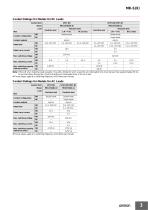
MK-S(X) Contact Ratings for Models for DC Loads Contact form Load Item Contact configuration Resistive load Resistive load Rated load Max. switching current Max. switching capacity (reference value) Rated carry current Note: If the L/R of an inductive load exceeds 7 ms with a Model for a DC Load, the arc interruption time must be less than approximately 50 ms to use the Relay. Design the circuit so that the arc interruption time is 50 ms or less. * These values apply to a switching frequency of 30 times per minute. Contact Ratings for Models for AC Loads Contact form Resistive load Resistive...
Open the catalog to page 3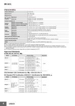
MK-S(X) Characteristics Contact resistance *1 Release time *2 Max. operating frequency Rated load Models for DC loads: 1,800 times/hour Models for AC loads: 1,200 times/hour Between coil and contacts Dielectric strength Between contacts of different polarity 2,500 VAC 50/60 Hz for 1 min between Between contacts of same polarity Vibration resistance 10 to 55 to 10 Hz, 0.75-mm single amplitude (1.5-mm double amplitude) 10 to 55 to 10 Hz, 0.50-mm single amplitude (1.0-mm double amplitude) Shock resistance Back-connecting Socket (P7M-06P) mounting: 1,000 m/s2 Front-connecting Socket (P7MF-06(-D))...
Open the catalog to page 4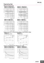
Engineering Data 100 DC resistive load 10 5 DC inductive load L/R = 7 ms DC inductive load DC13 class DC inductive load DC inductive load DC13 class DC13 class NO NC Ambient Temperature vs. Must Operate Voltage and Must Release Voltage MKS2XT-11 MKS2XT-11 Number of Relays: 5 DC Specification Must operate voltage Must release voltage Must operate/release voltage (%) Must operate/release voltage (%) Must operate voltage Must release voltage Load time constant (ms) Load time constant (ms)
Open the catalog to page 5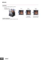
MK-S(X) Test Button The circuit can be checked using either of two modes. Test Button DC specification: Blue AC specification: Red Test Button Applications Example: Checking operation of Relays and sequence circuits. Press the button for operation. (No tool is required.) Lock the contacts by pressing down on the button and turning it.
Open the catalog to page 6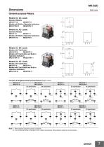
General-purpose Relays Models for DC Loads Standard Models MKS1XT-10 MKS2XT-11 Models with Built-in Operation Indicators MKS1XTN-10 MKS2XTN-11 Standard Models MKS1T-10 MKS2T-11 Models with Built-in Operation Indicators MKS1TN-10 MKS2TN-11 Models for DC Loads Models with Test Button MKS1XTI-10 MKS2XTI-11 Models with Test Button and Built-in Operation Indicators MKS1XTIN-10 MKS2XTIN-11 Models with Test Button MKS1TI-10 MKS2TI-11 Models with Test Button and Built-in Operation Indicators MKS1TIN-10 MKS2TIN-11 Terminal Arrangement/Internal Connection (Bottom View) MKS1XT-10 MKS1XTI-10 Note: 1. Wire...
Open the catalog to page 7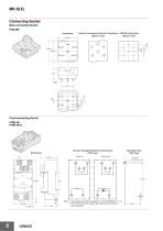
MK-S(X) Connecting Socket Back-connecting Socket P7M-06P Dimensions Terminal Arrangement/Internal Connections PCB Mounting Holes (Bottom View) (Bottom View) Terminal Arrangement/Internal Connections (TOP View) Mounting Holes (TOP View) Two, M4 or two 3.5-dia. hole Note: 1. The internal connections diagram is for the MKS2(X)T@@-11. 2. The P7MF-06-D has polarity. Be careful to wire with the correct polarity.
Open the catalog to page 8
MK-S(X) Accessory (Order Separately) Connecting Socket Socket Back-connecting Socket Front-connecting Socket Mounts to DIN Track or via screws Note: 1. The P7M-06P, P7MF-06, and P7MF-06-D can be used with models for DC loads with an SPST-NO or SPST-NO/SPST-NC contact form or with models for AC loads with an SPST-NO or SPST-NO/SPST-NC contact form. 2. The P7MF-06-D has a built-in diode and can thus be used only with Relays with DC operating coils. Do not use it with a Relay with an AC operating coil. 3. Refer to Gang Mounting on page 10 for the conditions required for gang mounting. Relay Hold-down...
Open the catalog to page 9
Safety Precautions Refer also to Precautions for All Relays. Precautions for Correct Use Installation Test Button • Models for DC loads (i.e., models with “X” in the model number) have permanent magnets built into the insulating block. If a permanent magnet or other magnetic body comes near the Relay, magnetic interference will occur with the built-in permanent magnet and the contact switching capacity will be decreased. • Models for AC loads do not contain a permanent magnet. • When mounting a P7MF-06(-D) Front-mounting Socket to a DIN Track, attach PFP-M End Plates on both sides of the Socket...
Open the catalog to page 10All OMRON catalogs and technical brochures
 D4F
D4F8 Pages
 D4GS-N
11 Pages
 E4E2
E4E25 Pages
 Fiber SensorBest Selection Catalog
104 Pages
 Fiber Unit E32-LT/LD
4 Pages
 G9SE Series
20 Pages
 NX-SL/SI/SO
20 Pages
 G9SP
G9SP28 Pages
 G9SX-SM
24 Pages
 G9SX-SM/LM
9 Pages
 G9SX/G9SX-GS
49 Pages
 G9SX-LM
28 Pages
 G9SB
G9SB10 Pages
 G9SA
G9SA16 Pages
 DST1 Series
5 Pages
 WS02-CFSC1-E
3 Pages
 G9SA-300-SC
9 Pages
 K8AK-AS
12 Pages
 K8AK-AW
16 Pages
 K8AK-VS
12 Pages
 K8AK-VW
12 Pages
 K8AK-PH
12 Pages
 K8DS-PH
12 Pages
 K8AK-PM
16 Pages
 K8DS-PM
12 Pages
 K8AK-PA
12 Pages
 K8DS-PA
12 Pages
 K8AK-PW
12 Pages
 K8DS-PU
12 Pages
 K8DS-PZ
12 Pages
 K8AK-TS/PT
12 Pages
 K8AK-LS
12 Pages
 K8AK-TH
12 Pages
 K2CM
K2CM16 Pages
 SE
SE15 Pages
 SAO
SAO13 Pages
 APR-S
APR-S6 Pages
 XS5
XS525 Pages
 XS2
XS229 Pages
 F92A
F92A4 Pages
 GLS
GLS3 Pages
 TL-L
TL-L5 Pages
 V680 series
68 Pages
 V680S Series
68 Pages
 MY
MY35 Pages
 E3NC-L/-S
16 Pages
 61F-GPN-BT / -BC
5 Pages
 NE1A-SCPU Series
8 Pages
![NE1A-SCPU0[]-EIP](https://img.directindustry.com/pdf/repository_di/15954/ne1a-scpu0-eip-616667_1mg.jpg) NE1A-SCPU0[]-EIP
NE1A-SCPU0[]-EIP8 Pages
 NE0A-SCPU01
6 Pages
 LY
LY14 Pages
![G2R-[]-S](https://img.directindustry.com/pdf/repository_di/15954/g2r-s-616653_1mg.jpg) G2R-[]-S
G2R-[]-S11 Pages
 G7T
G7T7 Pages
 G2A
G2A9 Pages
 G2A-434
7 Pages
 G2AK
G2AK7 Pages
 MK-S
MK-S9 Pages
 MM
MM17 Pages
 MMK
MMK14 Pages
 G4Q
G4Q6 Pages
 G7Z
G7Z9 Pages
 G7J
G7J10 Pages
 E4B
E4B12 Pages
 E4A-3K
9 Pages
 E4C-UDA
5 Pages
 E6H-C
E6H-C5 Pages
 E6F-C
E6F-C5 Pages
 E6D-C
E6D-C5 Pages
 E6B2-C
5 Pages
 E6A2-C
5 Pages
 NL
NL8 Pages
 VB
VB5 Pages
 SC
SC5 Pages
 D5F
D5F5 Pages
 D5A
D5A8 Pages
 E3S-GS3E4
3 Pages
 E3S-R
E3S-R11 Pages
 E3S-A
E3S-A21 Pages
 E3S-CL
9 Pages
 E3ZM-C
14 Pages
 E3T Data Sheet
26 Pages
 E3T Series
6 Pages
 G5 Series
59 Pages
 Sysmac Catalog
410 Pages
 VT-X700
6 Pages
 E5AC-T
8 Pages
 CP1
CP112 Pages
 CP1E
CP1E12 Pages
 MS4800
40 Pages
 VC-DL100
6 Pages
 FZ4 Series
42 Pages
 ZG2
ZG216 Pages
 ZS Series
32 Pages
 ZW Series
24 Pages
 E9NC-T
2 Pages
 Vision System FH series
54 Pages
 CompoNet
28 Pages
 F3SJ Series Safety Light Curtain
108 Pages
 Code Reader/OCR
24 Pages
 Fiber Sensor Best Selection Catalog
100 Pages
 Portable Multi-logger ZR-RX70
12 Pages
 Air Particle Sensor ZN-PD-S
2 Pages
 NT series
18 Pages
 Round Water-resistant Connectors
31 Pages
 Safety Controller G9SP
28 Pages
 E3FA PHOTOELECTRIC SENSORS
24 Pages
 Switch Mode Power Supply S8VK-G
22 Pages
 Data Logger ZR-RX Series
12 Pages
 Programmable Terminals NS Series
57 Pages
 DeviceNet Safety System
30 Pages
 Switching Power Supplies
16 Pages
 Photomicro Sensors
7 Pages
 Displacement Sensors
4 Pages
 R87F / R87T AC Axial Fans
28 Pages
 H8PS Cam Positioner
32 Pages
 OS32C Safety Laser Scanner
24 Pages
 FQ Vision Sensor
17 Pages
 ZN-PD Air Particle Sensor
16 Pages
 S8EX Switch Mode Power Supply
24 Pages
 CP1L CP series CP1L CPU Unit
36 Pages
 E2EF
E2EF8 Pages
 FQ2 Smart camera
24 Pages


Archived catalogs
 REGULATION SOLUTIONS
24 Pages
 Sensor Accessories
38 Pages
 SMART REMOTE I/O
12 Pages
 SAFETY APPLICATION HANDBOOK
55 Pages
 Vision Systems
20 Pages
- SARRALLE industrial robot
- Digital I/O
- Single-pole switch
- IO module
- Propeller fan
- Push-button switch
- SARRALLE air circulation fan
- Digital temperature control
- SARRALLE industrial fan
- Terminal box
- Switching relay
- Analog I/O
- SARRALLE digital indicator
- Digital IO module
- SARRALLE handling robot
- SARRALLE 3D software
- AC fan
- SARRALLE interface software
- SARRALLE panel-mount indicator
- SARRALLE simulation software