K2CM
1 /16Pages

K2CM
1 /16Pages
Catalog excerpts

Solid-state Relay Enables Choice of Three Operating Functions (Overcurrent, Open-phase, and Reverse-phase) • Protects 3-phase induction motors and their loads from damage. • Selection and combination of operating functions from overcurrent, open-phase, and reverse-phase. • Circuit and output relay operation can be checked by just operating the test button. • The set time value can be checked easily because operation time is indicated from the start of operation. • Space-saving, integrated construction. Note: If the K2CM is used with an inverter, the operating conditions will depend on the load wiring length, inverter carrier frequency, basic frequency, and load conditions. Error will occur in the operating values of the overload elements. It is recommended to test operation before using the K2CM. ■ Model Number Legend K2CM-nnn-nn 1 2 3 4 5 6 2. Mounting style None: Surface-mounting, integrated type 3. Operating time characteristics None: Inverse type Q: Instantaneous type 4. Supply voltage of control circuit 1: 100/110/120 VAC 6. Operating time None: x1 (2 to 10 s)/ x4 (8 to 40 s) Switchable 7. Resetting method None: Manual reset A: Automatic reset 8. Reverse-phase detection type None: Current reverse-phase detection V: Voltage reverse-phase detection Ordering Information ■ List of Models Voltage Reverse-phase Detection Models
Open the catalog to page 1
Current Reverse-phase Detection Models Note: The start-up lock timer restarts when the operating value at starting becomes less than 30% of the set current value.
Open the catalog to page 2
Note: This means that no malfunction occurs with the open-phase element, but the operating value of the overload element may vary.
Open the catalog to page 3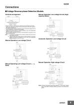
Connections ■ Voltage Reverse-phase Detection Models Manual Operation Low-voltage Circuit (Highcapacity Motor) Terminal Arrangement Stop Start Output contacts Control power (SPDT) supply • Perform the external connections by referring to the examples given below. • Obtain the control power supply from the same phase as the power supply to the magnet contactor coil. • Connect the phase advancing capacitors closer to the power supply than the current transformer, as shown in the examples. • Tighten the terminal screws to a torque of 0.98 N·m max. (The appropriate tightening torque is 0.49 to 0.67...
Open the catalog to page 4
■ Current Reverse-phase Detection Models Terminal Arrangement Manual Operation Low-voltage Circuit (Highcapacity Motor) 200 VAC 50/60Hz R S T Stop Start Output contacts Control power (NO and NC) supply • Perform the external connections by referring to the examples given below. • Connect the phase advancing capacitors closer to the power supply than the current transformer as shown in the examples. • Tighten the terminal screws to a torque of 0.98 N·m max. (The appropriate tightening torque is 0.49 to 0.67 N·m.) • Use of insulated solderless terminals is recommended for connection to the Relay...
Open the catalog to page 5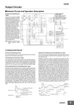
Output Circuits ■ Internal Circuit and Operation Description Reset circuit Voltage Reverse-phase Detection Models With the voltage reverse-phase detection models, the circuit section enclosed by A in the diagram on the left is configured as shown below. The circuit section enclosed by C is not used. Reset circuit Start time setting circuit Start-up detecting circuit Relay drive circuit Instantaneous Type With instantaneous-type models, the circuit section enclosed by B is configured as shown below. Overcurrent detecting circuit Open-phase detecting circuit Overcurrent indicator Open-phase indicator...
Open the catalog to page 6
K2CM 2) Open-phase Circuit T phase 1.0 Open-phase Level Detecting Circuit Open-phase Maximum phase of switch current: R phase = 1.0 "High" This circuit detects when the current reaches the open-phase operating level (85% max. of the set current value). Therefore, open-phase is not detected until the maximum phase of the current exceeds 85% of the set current value. The following imbalance factors can be selected by setting the openphase switch. “High” . . .Operating imbalance factor: 35 ±10% “Low” . . .Operating imbalance factor: 60% min. The imbalance factor can be easily obtained from the following...
Open the catalog to page 7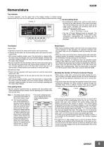
Nomenclature Trip Indicator Test Button Current-setting Knob • By operating the setting knob, set the current value to be equal to the rated current of the motor to be used. The current-setting knob uses the same scale as the rated current. Therefore, the operating value will be 115% of the set current value. Example: Operating current value = 12 x 1.15 (115%) = 13.8 A • The List of Current Settings shows an example. The rated current differs depending on the motor’s type, construction, manufacturer, etc. Therefore, set the operating current after checking the specifications of the motor. • The...
Open the catalog to page 8
3. Reverse-phase Setting Switches When the motor circuit trips due to overcurrent, open-phase, or reverse-phase, the respective LED indicator lights (continuously). The overcurrent indicator also indicates the start of operation. These switches select the reverse-phase detection function and reverse-phase polarity. By selecting the reverse-phase polarity accordingly, the K2CM can operate normally without changing the connections when wired with the order of the phases reversed. Start Trip • With the inverse-type models, when the motor current exceeds the overcurrent operating value, the overcurrent...
Open the catalog to page 9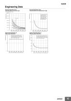
Engineering Data Overload Operating Time Characteristics for Instantaneous Type Overload Operating Time Characteristics for Inverse Type Time scale multiplying factor (x 4) (x 1) Typical Characteristics of Open-phase Operation Typical Characteristics of Reverse-phase Operation Motor current (percentage of current-setting value) Motor current (percentage of current-setting value)
Open the catalog to page 10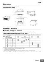
Dimensions Note: All units are in millimeters unless otherwise indicated. Four, 6-dia. mounting holes or four, M5 mounting-screw holes 120 Operating Procedures ■ Operation, Setting, and Indication Based on the current value of the motor to be used, perform the setting of each item of the K2CM Motor Protective Relay. List of Current Settings (when using a 200-VAC motor) Type* Setting Time scale value Current setting range (A) The squares (@) represent the symbols defined under Model Number Legend. ** The rated current is the current at full load. *** Supply: Low-voltage 3-phase basket type inductive...
Open the catalog to page 11All OMRON catalogs and technical brochures
 D4F
D4F8 Pages
 D4GS-N
11 Pages
 E4E2
E4E25 Pages
 Fiber SensorBest Selection Catalog
104 Pages
 Fiber Unit E32-LT/LD
4 Pages
 G9SE Series
20 Pages
 NX-SL/SI/SO
20 Pages
 G9SP
G9SP28 Pages
 G9SX-SM
24 Pages
 G9SX-SM/LM
9 Pages
 G9SX/G9SX-GS
49 Pages
 G9SX-LM
28 Pages
 G9SB
G9SB10 Pages
 G9SA
G9SA16 Pages
 DST1 Series
5 Pages
 WS02-CFSC1-E
3 Pages
 G9SA-300-SC
9 Pages
 K8AK-AS
12 Pages
 K8AK-AW
16 Pages
 K8AK-VS
12 Pages
 K8AK-VW
12 Pages
 K8AK-PH
12 Pages
 K8DS-PH
12 Pages
 K8AK-PM
16 Pages
 K8DS-PM
12 Pages
 K8AK-PA
12 Pages
 K8DS-PA
12 Pages
 K8AK-PW
12 Pages
 K8DS-PU
12 Pages
 K8DS-PZ
12 Pages
 K8AK-TS/PT
12 Pages
 K8AK-LS
12 Pages
 K8AK-TH
12 Pages
 SE
SE15 Pages
 SAO
SAO13 Pages
 APR-S
APR-S6 Pages
 XS5
XS525 Pages
 XS2
XS229 Pages
 F92A
F92A4 Pages
 GLS
GLS3 Pages
 TL-L
TL-L5 Pages
 V680 series
68 Pages
 V680S Series
68 Pages
 MY
MY35 Pages
 E3NC-L/-S
16 Pages
 61F-GPN-BT / -BC
5 Pages
 NE1A-SCPU Series
8 Pages
![NE1A-SCPU0[]-EIP](https://img.directindustry.com/pdf/repository_di/15954/ne1a-scpu0-eip-616667_1mg.jpg) NE1A-SCPU0[]-EIP
NE1A-SCPU0[]-EIP8 Pages
 NE0A-SCPU01
6 Pages
 LY
LY14 Pages
![G2R-[]-S](https://img.directindustry.com/pdf/repository_di/15954/g2r-s-616653_1mg.jpg) G2R-[]-S
G2R-[]-S11 Pages
 G7T
G7T7 Pages
 G2A
G2A9 Pages
 G2A-434
7 Pages
 G2AK
G2AK7 Pages
 MK-S
MK-S9 Pages
 MK-S(X)
12 Pages
 MM
MM17 Pages
 MMK
MMK14 Pages
 G4Q
G4Q6 Pages
 G7Z
G7Z9 Pages
 G7J
G7J10 Pages
 E4B
E4B12 Pages
 E4A-3K
9 Pages
 E4C-UDA
5 Pages
 E6H-C
E6H-C5 Pages
 E6F-C
E6F-C5 Pages
 E6D-C
E6D-C5 Pages
 E6B2-C
5 Pages
 E6A2-C
5 Pages
 NL
NL8 Pages
 VB
VB5 Pages
 SC
SC5 Pages
 D5F
D5F5 Pages
 D5A
D5A8 Pages
 E3S-GS3E4
3 Pages
 E3S-R
E3S-R11 Pages
 E3S-A
E3S-A21 Pages
 E3S-CL
9 Pages
 E3ZM-C
14 Pages
 E3T Data Sheet
26 Pages
 E3T Series
6 Pages
 G5 Series
59 Pages
 Sysmac Catalog
410 Pages
 VT-X700
6 Pages
 E5AC-T
8 Pages
 CP1
CP112 Pages
 CP1E
CP1E12 Pages
 MS4800
40 Pages
 VC-DL100
6 Pages
 FZ4 Series
42 Pages
 ZG2
ZG216 Pages
 ZS Series
32 Pages
 ZW Series
24 Pages
 E9NC-T
2 Pages
 Vision System FH series
54 Pages
 CompoNet
28 Pages
 F3SJ Series Safety Light Curtain
108 Pages
 Code Reader/OCR
24 Pages
 Fiber Sensor Best Selection Catalog
100 Pages
 Portable Multi-logger ZR-RX70
12 Pages
 Air Particle Sensor ZN-PD-S
2 Pages
 NT series
18 Pages
 Round Water-resistant Connectors
31 Pages
 Safety Controller G9SP
28 Pages
 E3FA PHOTOELECTRIC SENSORS
24 Pages
 Switch Mode Power Supply S8VK-G
22 Pages
 Data Logger ZR-RX Series
12 Pages
 Programmable Terminals NS Series
57 Pages
 DeviceNet Safety System
30 Pages
 Switching Power Supplies
16 Pages
 Photomicro Sensors
7 Pages
 Displacement Sensors
4 Pages
 R87F / R87T AC Axial Fans
28 Pages
 H8PS Cam Positioner
32 Pages
 OS32C Safety Laser Scanner
24 Pages
 FQ Vision Sensor
17 Pages
 ZN-PD Air Particle Sensor
16 Pages
 S8EX Switch Mode Power Supply
24 Pages
 CP1L CP series CP1L CPU Unit
36 Pages
 E2EF
E2EF8 Pages
 FQ2 Smart camera
24 Pages


Archived catalogs
 REGULATION SOLUTIONS
24 Pages
 Sensor Accessories
38 Pages
 SMART REMOTE I/O
12 Pages
 SAFETY APPLICATION HANDBOOK
55 Pages
 Vision Systems
20 Pages
- SARRALLE industrial robot
- Digital I/O
- Single-pole switch
- IO module
- Propeller fan
- Push-button switch
- SARRALLE air circulation fan
- Digital temperature control
- Terminal box
- SARRALLE industrial fan
- Analog I/O
- Switching relay
- SARRALLE digital indicator
- Digital IO module
- SARRALLE handling robot
- SARRALLE 3D software
- AC fan
- SARRALLE interface software
- SARRALLE panel-mount indicator
- SARRALLE simulation software