

G9SX-SM

G9SX-SM
- Monitors standstill via BEMF signal.
- Standard Configuration for immediate use without sensitivity adjustment.
- User Configuration for fine-tuning sensitivity.
- LED indications for easy fault diagnosis.
- Certified for Safety Category 4 (EN954-1), PLe (ISO13849-1), SIL 3 (IEC/EN 62061).
- Rated supply voltage: 24 VDC.
- Power consumption: 4 W max.
- Standstill detection input voltage: 480 VAC max.
- Safety standstill detection output: Source output (PNP), load current: 0.3 A DC max.
- Response time: 50 ms max.
- Detection voltage: 10 mV max (Standard), 100 mV max (User).
- Insulation resistance: 100 MΩ min.
- Dielectric strength: 2,000 VAC for 1 min.
- Standard Configuration: Detects standstill when input voltage is 10 mV or less.
- User Configuration: Allows tuning of standstill determining time with Tuning and Monitoring Modes.
- Standstill Detection Input 2: Issues include wiring failures, inverter dynamic brake settings, and circuit failures. Solutions involve checking wiring, setting brake time under 30 seconds, and replacing faulty products.
- Standstill Detection Input Frequency: Ensure motor operation frequency is 120Hz or less.
- EDM Input: Problems may arise from wiring failures, electromagnetic disturbances, or circuit failures. Solutions include checking wiring, separating wiring from power lines, and replacing faulty products.
- Safety Standstill Detection Outputs: Issues include wiring failures, electromagnetic disturbances, circuit failures, and high ambient temperatures. Solutions involve checking wiring, separating wiring from power lines, replacing faulty products, and checking ambient conditions.
- Operation Mode Settings: Incorrect preset switch values and circuit failures can occur. Solutions include checking preset switch values and replacing faulty products.
- Supply Voltage: Ensure supply voltage is within the rated value for G9SX units.
- Standard Configuration: Describes LED indications and machine operations for standard configurations.
- User Configuration and Tuning Mode: Details the process for setting operation and mode preset switches, and tuning procedures to ensure proper machine operation.
- Monitoring Mode: Outlines the steps for setting up and monitoring machine operations, including LED indications and output statuses.
- Ensure safety outputs are not overloaded and that G9SX-SM is not used in systems with multiple motors driven by one inverter or contactor.
- Proper wiring is crucial to prevent loss of safety functions. Use appropriate protection circuitry and ensure correct voltage applications.
- Auxiliary outputs are not safety outputs and should not be used as such.
- Qualified personnel should handle installation, testing, and maintenance. Regular inspections are necessary to ensure proper functioning.
- Do not dismantle or modify G9SX-SM, and use components that comply with relevant safety standards.
- Disconnect power when wiring to prevent electric shock, and avoid use in combustible or explosive environments.
- Guard Lock Safety-door Switch: Use devices with Direct Opening Mechanism compliant with IEC/EN 60947-5-1, mechanical lock type, and solenoid coil 24VDC, less than 300mA.
- Safety Relay: Use devices with forcibly guided contacts compliant with EN 50205, capable of switching micro loads of 24VDC, 5mA.
- Contactor: Use devices compliant with IEC/EN 60947-4-1 for auxiliary contact linked with power contact, capable of switching micro loads of 24VDC, 5mA.
- Other Devices: Ensure devices meet safety category level requirements.
- Handle G9SX-SM with care to avoid damage from drops or excessive vibration.
- Store in conditions avoiding direct sunlight, extreme temperatures, high humidity, corrosive gases, and mechanical shocks.
- Mount on DIN rails with proper spacing for ventilation and wiring.
- Use cables less than 100m for specific inputs and ensure separate installation from other signal lines.
- Set appropriate Standstill determining time and switch from Tuning Mode to Monitoring Mode after tuning.
- Ensure safety standstill detection outputs are used correctly and consider safety distance delays.
- Connect terminal A2 to ground to prevent electromagnetic disturbances.
- G9SX-SM is certified by TÜV-SUD and UL, compliant with various international standards including EN954-1 Cat.4, IEC/EN61508 SIL3, and ISO13849-1 PLe.
- OMRON provides a one-year warranty against defects in materials and workmanship.
- OMRON disclaims all other warranties and limits liability to the product's price.
- OMRON is not responsible for conformity with standards or regulations in customer applications.
- Ensure the system as a whole addresses risks, especially in applications involving serious risk to life or property.
- Specifications may change without notice; confirm actual specifications with OMRON representatives.
- Performance data is a guide and does not constitute a warranty.
Catalog excerpts
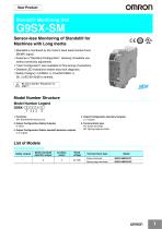
omRon Standstill Monitoring Unit Sensor-less Monitoring of Standstill for Machines with Long Inertia • Standstill is monitored by the motor's back electromotive force (BEMF) signal. • Features a "Standard Configuration", allowing immediate use without sensitivity adjustment. • "User Configuration" also available for fine-tuning of sensitivity. • Detailed LED indications enable easy fault diagnosis. •Safety Category 4 (EN954-1), PLe(ISO13849-1), SIL 3 (IEC/EN 62061) certified. Be sure to read the "Precautions" on page 17. Model Number Structure Model Number Legend G9SX- □□□ III III - □□ 1 2 3 4 5 1. Functions 4. Output Configuration (Auxiliary Outputs) SM: Standstill Monitoring Unit 2: 2 outputs 5. Terminal block type RT: Screw terminals RC: Spring-cage terminals 2. Output Configuration (Safety Outputs) 0: None 3. Output Configuration (Safety standstill detection outputs) 3: 3 outputs Standstill Monitoring Unit
Open the catalog to page 1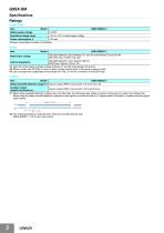
Ratings Power input *1. While safety standstill detection outputs are in the ON state, the following pulse signal is output continuously for output circuit diagnosis. When using the safety standstill detection outputs as input signals to control devices (i.e. Programmable Controllers), consider the pulse signal shown below. *2. The following derating is required when Units are mounted side-by-side. G9SX-SM032-D: 0.2 A max. load current
Open the catalog to page 2
* For G9SX-SM032-RT (with screw terminals)
Open the catalog to page 3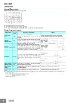
Connect Z1 and Z2 to the motor lines respectively. Connect Z3 and Z4 to the motor lines respectively. Keep these outputs Open when NOT used. Keep these outputs Open when NOT used. Keep these outputs Open when NOT used. Connect the power supply plus to the A1 terminal. Connect the power supply minus to the A2 terminal. * For protecting the motor against short-circuit due to incorrect wiring, etc., apply overcurrent protective equipment: fuses, circuit-breaker, etc., with the ratings below. Rated voltage: Greater than standstill detection inputs (voltage supplied to the motor) Rated current: 3A...
Open the catalog to page 4
Functions Configuration and Mode Use the "Operation Preset switch” on the back side to select either Standard Configuration or User Configuration. The selected configuration mode is enabled at power-on. Normally, please use Standard Configuration which is set as factory default. If the standstill determining time is found too long in the Standard Configuration mode, switch to User Configuration and adjust the standstill determining time. Standard Configuration When G9SX-SM detects that the standstill detection input voltage is 10 mV or less, it will turn on safety standstill detection outputs,...
Open the catalog to page 5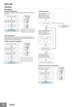
G9SX-SM Operation Functions Standard Configuration "Standard Configuration" allows standstill detection without tuning sensitivity. Wire inputs and outputs Set the standstill determining time preset switch on the front side to 1 second and test the actual machine standstill timing t1 and t2 of ES indication (auxiliary output X1) turning on Set the operation preset switch on the back side to "STD" Timing t2 is ahead Turn the power ON Starting up under Standard Configuration Use under the "Standard Configuration" To u s e u n d e r t h e " S t a n d a r d Configuration," set the operation preset...
Open the catalog to page 6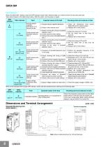
Fault Detection When the G9SX-SMD detects a fault, the ERR indicator and/or other indicators light up or blink to inform the user about the fault. Take actions based on the table shown below. After the action, turn the power on again. Dimensions and Terminal ArrangementStandstill Monitoring Unit G9SX-SM032-D Terminal arrangement ©(§) @@<S a)
Open the catalog to page 8
Application Examples G9SX-SM032 (24 VDC) (3-phase Induction Motor) + G9SX-AD322-T15 (24 VDC) (Guard Lock Safety Door Switch, 2-channel Safety Limit Switch Inputs/Manual Reset) ** Feedback loop Lock release switch S5 Guard Lock Safety Door Switch S1: Guard Lock Safety Door Switch S2: Safety limit switch S3: Stop signal S4: Reset switch S5: Lock release switch KM1, KM2: Contactor M: 3-phase induction motor Timing Chart Guard opened → closed Guard closed →opened Guard Lock Safety Door Switch S1 Control circuit Safety limit switch S2 Reset switch S4 KM1, KM2 N.C. contact KM1, KM2 N.O. contact Note:...
Open the catalog to page 9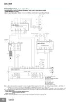
G9SX-SM G9SX-SM032 (24 VDC) (3-phase Induction Motor) + G9SX-BC202 (24 VDC) (2-channel Emergency Stop Switch Inputs/Manual Reset) + G9SX-GS226-T15 (24 VDC) (Guard Lock Safety Door Switch + 2-channel Safety Limit Switch Inputs/Manual Reset) ** Reset switch Emergency Stop Switch Lock release switch S6 Guard Lock Safety-door Switch Control circuit Feedback loop Control circuit S1: Emergency Stop Switch S2: Reset switch S3: Guard Lock Safety Door Switch S4: Safety limit switch S5: Reset switch S6: Lock release switch KM1, KM2: Contactor M: 3-phase induction motor Note: 1. This circuit example is...
Open the catalog to page 10
G9SX-SM Timing Chart Emergency Stop Switch S1 Reset switch S2 Guard opened → closed Guard closed → opened Guard Lock Safetydoor Switch S3 Guard can be opened. Safety Limit Switch S4 Logical AND connection input T41 Reset switch S5 KM1, KM2 NC contact KM1, KM2 NO contact Inverter operation (signal for motor) Inertial rotation condition Motor rotation Standstill detection input 1 voltage Standstill detection input 2 voltage Lock release signal Safety standstill detection output ES Lock release switch S6
Open the catalog to page 11
G9SX-SM G9SX-SM032 (24 VDC) (3-phase Induction Motor with Star-Delta wiring) + G9SX-BC202 (24 VDC) (Guard Lock Safety Door Switch + 2-channel Safety Limit Switch inputs/Manual Reset) ** Lock release switch S5 S1: Guard lock Safety-door Switch S2: Safety Limit Switch S3: Stop signal S4: Reset switch S5: Lock release switch KM1, KM2: Contactor KM3, KM4: Contactor for star-delta starter M: 3-phase induction motor Guard Lock Safety Door Switch Timing Chart Guard Guard opened → closed Guard Lock Safety Door Switch S1 Safety limit switch S2 Control circuit Motor rotation X1 X2 Standstill detection...
Open the catalog to page 12All OMRON catalogs and technical brochures
Archived catalogs
 D4F
D4F8 Pages
 D4GS-N
11 Pages
 E4E2
E4E25 Pages
 Fiber SensorBest Selection Catalog
104 Pages
 Fiber Unit E32-LT/LD
4 Pages
 G9SE Series
20 Pages
 R87F / R87T AC Axial Fans
28 Pages
 Displacement Sensors
4 Pages
 Photomicro Sensors
7 Pages
 Switching Power Supplies
16 Pages
 DeviceNet Safety System
30 Pages
 Programmable Terminals NS Series
57 Pages
 Data Logger ZR-RX Series
12 Pages
 Switch Mode Power Supply S8VK-G
22 Pages
 E3FA PHOTOELECTRIC SENSORS
24 Pages
 Safety Controller G9SP
28 Pages
 Round Water-resistant Connectors
31 Pages
 NT series
18 Pages
 Air Particle Sensor ZN-PD-S
2 Pages
 Portable Multi-logger ZR-RX70
12 Pages
 Fiber Sensor Best Selection Catalog
100 Pages
 Code Reader/OCR
24 Pages
 F3SJ Series Safety Light Curtain
108 Pages
 CompoNet
28 Pages
 Vision System FH series
54 Pages
 E9NC-T
2 Pages
 ZW Series
24 Pages
 ZS Series
32 Pages
 ZG2
ZG216 Pages
 FZ4 Series
42 Pages
 VC-DL100
6 Pages
 MS4800
40 Pages
 CP1E
CP1E12 Pages
 CP1
CP112 Pages
 E5AC-T
8 Pages
 H8PS Cam Positioner
32 Pages
 OS32C Safety Laser Scanner
24 Pages
 FQ Vision Sensor
17 Pages
 ZN-PD Air Particle Sensor
16 Pages
 S8EX Switch Mode Power Supply
24 Pages
 CP1L CP series CP1L CPU Unit
36 Pages
 E2EF
E2EF8 Pages
 FQ2 Smart camera
24 Pages
 VT-X700
6 Pages
 Sysmac Catalog
410 Pages
 G5 Series
59 Pages
 E3T Series
6 Pages
 E3T Data Sheet
26 Pages
 E3ZM-C
14 Pages
 E3S-CL
9 Pages
 E3S-A
E3S-A21 Pages
 E3S-R
E3S-R11 Pages
 E3S-GS3E4
3 Pages
 D5A
D5A8 Pages
 D5F
D5F5 Pages
 SC
SC5 Pages
 VB
VB5 Pages
 NL
NL8 Pages
 E6A2-C
5 Pages
 E6B2-C
5 Pages
 E6D-C
E6D-C5 Pages
 E6F-C
E6F-C5 Pages
 E6H-C
E6H-C5 Pages
 E4C-UDA
5 Pages
 E4A-3K
9 Pages
 E4B
E4B12 Pages
 G7J
G7J10 Pages
 G7Z
G7Z9 Pages
 G4Q
G4Q6 Pages
 MMK
MMK14 Pages
 MM
MM17 Pages
 MK-S(X)
12 Pages
 MK-S
MK-S9 Pages
 G2AK
G2AK7 Pages
 G2A-434
7 Pages
 G2A
G2A9 Pages
 G7T
G7T7 Pages
![G2R-[]-S](https://img.directindustry.com/pdf/repository_di/15954/g2r-s-616653_1mg.jpg) G2R-[]-S
G2R-[]-S11 Pages
 LY
LY14 Pages
 NE0A-SCPU01
6 Pages
![NE1A-SCPU0[]-EIP](https://img.directindustry.com/pdf/repository_di/15954/ne1a-scpu0-eip-616667_1mg.jpg) NE1A-SCPU0[]-EIP
NE1A-SCPU0[]-EIP8 Pages
 NE1A-SCPU Series
8 Pages
 61F-GPN-BT / -BC
5 Pages
 E3NC-L/-S
16 Pages
 MY
MY35 Pages
 V680S Series
68 Pages
 V680 series
68 Pages
 TL-L
TL-L5 Pages
 GLS
GLS3 Pages
 F92A
F92A4 Pages
 XS2
XS229 Pages
 XS5
XS525 Pages
 APR-S
APR-S6 Pages
 SAO
SAO13 Pages
 SE
SE15 Pages
 K2CM
K2CM16 Pages
 K8AK-TH
12 Pages
 K8AK-LS
12 Pages
 K8AK-TS/PT
12 Pages
 K8DS-PZ
12 Pages
 K8DS-PU
12 Pages
 K8AK-PW
12 Pages
 K8DS-PA
12 Pages
 K8AK-PA
12 Pages
 K8DS-PM
12 Pages
 K8AK-PM
16 Pages
 K8DS-PH
12 Pages
 K8AK-PH
12 Pages
 K8AK-VW
12 Pages
 K8AK-VS
12 Pages
 K8AK-AW
16 Pages
 K8AK-AS
12 Pages
 G9SA-300-SC
9 Pages
 WS02-CFSC1-E
3 Pages
 DST1 Series
5 Pages
 G9SA
G9SA16 Pages
 G9SB
G9SB10 Pages
 G9SX-LM
28 Pages
 G9SX/G9SX-GS
49 Pages
 G9SX-SM/LM
9 Pages
 G9SP
G9SP28 Pages
 NX-SL/SI/SO
20 Pages
 REGULATION SOLUTIONS
24 Pages
 Sensor Accessories
38 Pages
 SMART REMOTE I/O
12 Pages
 SAFETY APPLICATION HANDBOOK
55 Pages
 Vision Systems
20 Pages


