G9SE Series
1 /20Pages

G9SE Series
1 /20Pages
Catalog excerpts

» Simple wiring using Push-In Plus terminal block » Slim design to save mounting space » Easy maintenance with status indicators
Open the catalog to page 1
Compact and easy-to-install units with safety outputs Helps increase your productivity, from installation to mainte Omron's new G9SE series of safety relay units offers an easy approach for various simple safety applications. The G9SE saves mounting space, lowers installation cost with Push-In Plus terminal block, and reduces operational cost with intuitive diagnostic indicators. 17.5 mm Slim design to save mounting space The slim design of only 17.5 or 22.5 mm saves space in the control panel. [Applicable safety standards] EN ISO 13849-1: PLe/Safety Category 4 IEC 62061: SIL3 EN81-1/-2/-20/50...
Open the catalog to page 2
nance For various safety input devices A wide variety of safety input devices such as emergency stop switches, door switches, and light curtains can be connected. OFF-delayed safety output models are also available. 2 safety outputs with OFF-delay Door switch Door switch Door switch Opto sensor Opto sensor Opto sensor Safety OFF-delay contact
Open the catalog to page 3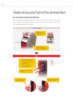
Simple wiring using Push-In Plus terminal block Easy and reliable installation and maintenance When the conventional model with terminals on the top and bottom of the unit is installed in a small control panel, it is difficult to secure sufficient space for wiring. The Push-In Plus terminal block on the front of the G9SE make installation easier and much quicker. Conventional Models ∙ Difficult to use the to screwdriver for wiring rear terminals Terminal No. distinguish rear ∙ Difficult todue to showing their terminals numbers on the front of the unit G9SE insert ∙ No tool required. Justwiring. the...
Open the catalog to page 4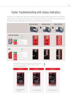
Faster troubleshooting with status indicators The indicators of conventional safety relay units only indicate the operating status of the internal relays (K1/K2), and it is difficult to check the operation or connection of safety input devices. The new intuitive LED indicators of the G9SE show the operating status of safety inputs and outputs, enabling faster and more accurate troubleshooting when the equipment stops. When the G9SE detects an error, such as input wiring, an indicator will blink to show where the error has occurred. This minimizes downtime to identify the cause when the equipment...
Open the catalog to page 5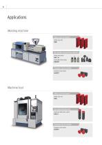
Applications Molding machine Safety circuit for machine Safety relay unit G9SE Door position and open/close detection Safety limit switch D4B-□N Small safety limit switch D4N/D4F Emergency stop for machine Emergency stop switch A22NE-P Machine tool Safety circuit for machine Safety relay unit G9SE Door open/close detection Guard lock safety-door switch D4SL-N Emergency stop for machine Emergency stop switch A22NE-P
Open the catalog to page 6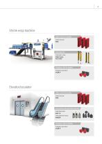
Shrink-wrap machine Safety circuit for machine Safety relay unit G9SE Detecting entry Safety light curtain F3SG-R series F3SJ series Emergency stop for machine Emergency stop switch A22NE-P Elevator/escalator Safety ci circuit for machine Safety relay unit rela G9SE Door pos position and open/close detection Safety limi switch limit D4B-□N Small safe limit switch safety D4N/D4F Emergenc Emergency stop for machine Emergency stop switch A22NE-P
Open the catalog to page 7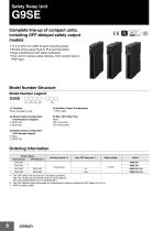
Safety Relay Unit Complete line-up of compact units, including OFF-delayed safety output models • 17.5 or 22.5 mm width to save mounting space • Simple wiring using Push-In Plus terminal block • Easy maintenance with status indicators • One unit for various safety devices, from contact input to PNP input Model Number Structure Model Number Legend G9SE - (1) Function None: Emergency stop (3) Safety Output Configuration (OFF-delayed Output) 0: None 2: DPST-NO (4) Auxiliary Output Configuration 1: PNP output Ordering Information *1 The OFF-delay time can be set in 16 steps as follows: T05: 0/0.1/0.2/0.3/0.4/0.5/0.6/0.7/0.8/1/1.5/2/2.5/3/4/5...
Open the catalog to page 8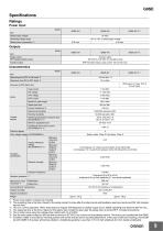
Power Input *1 Power consumption of loads not included. *2 The operating time is the time it takes for the safety contact to close after the safety inputs and feedback-reset input are turned ON. Not includes bounce time. *3 This is in normal operation. When executing non-regular self-diagnosis for Safety output circuit, G9SE operating time become 500 ms max.. *4 The response time is the time it takes for the safety main contact to open after the safety input is turned OFF. Includes bouncetime. *5 This is initial value using the voltage-drop method with 1A at 5VDC. *6 Use for each contact output...
Open the catalog to page 9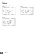
Connection Internal Connection G9SE-201 A^Tr^Tl^Ta^Ta^T^j)-[] Power supply circuit Reset/ Feedback Input Auxiliary Output Safety Outputs (instanta neous) Reset/ Feedback Input Auxiliary Output Power supply circuit
Open the catalog to page 10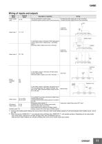
G9SE Wiring of inputs and outputs Signal Name Power supply input The input terminals for power supply. Connect the power supply plus to the A1 terminal. Connect the power source to the A1 and A2 terminals. Connect the power supply minus to the A2 terminal. 1-channel Safety input Safety input 1 T11 T12 T21 T22 Safety sensor To set Safety outputs in ON state, HIGH state signals must be input to both of Safety input 1 and Safety input 2. Otherwise Safety outputs cannot be in ON state. Feedback loop To set Safety outputs in ON state, ON state signal must be input to T33. Otherwise Safety outputs...
Open the catalog to page 11
Appearance and Explanation of Each Parts Type G9SE-201 Type G9SE-201 Type G9SE-201@ OFF-delay time preset switch Power Supply Reset/Feedback Input Auxiliary output Safety Outputs (Instantaneous) Safety Outputs (OFF-delay) Dimensions and Terminal arrangement Terminal arrangement and LED indicators G9SE-201 Mounting holes Type G9SE-201 Type G9SE-401 Type G9SE-221-T@
Open the catalog to page 12
Application Examples Highest achievable PL/ safety category Note: The above PL is only the evaluation result of the example. The PL must be evaluated in an actual application by the customer after confirming the usage conditions. •Application Overview • Immediately removes power to motor M when emergency stop switch S1 is pressed. • The power to motor M is kept removed until emergency stop switch S1 is released and reset switch S2 is pressed. Timing Chart S1: Emergency stop switch S2: Reset switch KM1, KM2: Magnetic contactor M: Motor
Open the catalog to page 13All OMRON catalogs and technical brochures
 D4F
D4F8 Pages
 D4GS-N
11 Pages
 E4E2
E4E25 Pages
 Fiber SensorBest Selection Catalog
104 Pages
 Fiber Unit E32-LT/LD
4 Pages
 NX-SL/SI/SO
20 Pages
 G9SP
G9SP28 Pages
 G9SX-SM
24 Pages
 G9SX-SM/LM
9 Pages
 G9SX/G9SX-GS
49 Pages
 G9SX-LM
28 Pages
 G9SB
G9SB10 Pages
 G9SA
G9SA16 Pages
 DST1 Series
5 Pages
 WS02-CFSC1-E
3 Pages
 G9SA-300-SC
9 Pages
 K8AK-AS
12 Pages
 K8AK-AW
16 Pages
 K8AK-VS
12 Pages
 K8AK-VW
12 Pages
 K8AK-PH
12 Pages
 K8DS-PH
12 Pages
 K8AK-PM
16 Pages
 K8DS-PM
12 Pages
 K8AK-PA
12 Pages
 K8DS-PA
12 Pages
 K8AK-PW
12 Pages
 K8DS-PU
12 Pages
 K8DS-PZ
12 Pages
 K8AK-TS/PT
12 Pages
 K8AK-LS
12 Pages
 K8AK-TH
12 Pages
 K2CM
K2CM16 Pages
 SE
SE15 Pages
 SAO
SAO13 Pages
 APR-S
APR-S6 Pages
 XS5
XS525 Pages
 XS2
XS229 Pages
 F92A
F92A4 Pages
 GLS
GLS3 Pages
 TL-L
TL-L5 Pages
 V680 series
68 Pages
 V680S Series
68 Pages
 MY
MY35 Pages
 E3NC-L/-S
16 Pages
 61F-GPN-BT / -BC
5 Pages
 NE1A-SCPU Series
8 Pages
![NE1A-SCPU0[]-EIP](https://img.directindustry.com/pdf/repository_di/15954/ne1a-scpu0-eip-616667_1mg.jpg) NE1A-SCPU0[]-EIP
NE1A-SCPU0[]-EIP8 Pages
 NE0A-SCPU01
6 Pages
 LY
LY14 Pages
![G2R-[]-S](https://img.directindustry.com/pdf/repository_di/15954/g2r-s-616653_1mg.jpg) G2R-[]-S
G2R-[]-S11 Pages
 G7T
G7T7 Pages
 G2A
G2A9 Pages
 G2A-434
7 Pages
 G2AK
G2AK7 Pages
 MK-S
MK-S9 Pages
 MK-S(X)
12 Pages
 MM
MM17 Pages
 MMK
MMK14 Pages
 G4Q
G4Q6 Pages
 G7Z
G7Z9 Pages
 G7J
G7J10 Pages
 E4B
E4B12 Pages
 E4A-3K
9 Pages
 E4C-UDA
5 Pages
 E6H-C
E6H-C5 Pages
 E6F-C
E6F-C5 Pages
 E6D-C
E6D-C5 Pages
 E6B2-C
5 Pages
 E6A2-C
5 Pages
 NL
NL8 Pages
 VB
VB5 Pages
 SC
SC5 Pages
 D5F
D5F5 Pages
 D5A
D5A8 Pages
 E3S-GS3E4
3 Pages
 E3S-R
E3S-R11 Pages
 E3S-A
E3S-A21 Pages
 E3S-CL
9 Pages
 E3ZM-C
14 Pages
 E3T Data Sheet
26 Pages
 E3T Series
6 Pages
 G5 Series
59 Pages
 Sysmac Catalog
410 Pages
 VT-X700
6 Pages
 E5AC-T
8 Pages
 CP1
CP112 Pages
 CP1E
CP1E12 Pages
 MS4800
40 Pages
 VC-DL100
6 Pages
 FZ4 Series
42 Pages
 ZG2
ZG216 Pages
 ZS Series
32 Pages
 ZW Series
24 Pages
 E9NC-T
2 Pages
 Vision System FH series
54 Pages
 CompoNet
28 Pages
 F3SJ Series Safety Light Curtain
108 Pages
 Code Reader/OCR
24 Pages
 Fiber Sensor Best Selection Catalog
100 Pages
 Portable Multi-logger ZR-RX70
12 Pages
 Air Particle Sensor ZN-PD-S
2 Pages
 NT series
18 Pages
 Round Water-resistant Connectors
31 Pages
 Safety Controller G9SP
28 Pages
 E3FA PHOTOELECTRIC SENSORS
24 Pages
 Switch Mode Power Supply S8VK-G
22 Pages
 Data Logger ZR-RX Series
12 Pages
 Programmable Terminals NS Series
57 Pages
 DeviceNet Safety System
30 Pages
 Switching Power Supplies
16 Pages
 Photomicro Sensors
7 Pages
 Displacement Sensors
4 Pages
 R87F / R87T AC Axial Fans
28 Pages
 H8PS Cam Positioner
32 Pages
 OS32C Safety Laser Scanner
24 Pages
 FQ Vision Sensor
17 Pages
 ZN-PD Air Particle Sensor
16 Pages
 S8EX Switch Mode Power Supply
24 Pages
 CP1L CP series CP1L CPU Unit
36 Pages
 E2EF
E2EF8 Pages
 FQ2 Smart camera
24 Pages


Archived catalogs
 REGULATION SOLUTIONS
24 Pages
 Sensor Accessories
38 Pages
 SMART REMOTE I/O
12 Pages
 SAFETY APPLICATION HANDBOOK
55 Pages
 Vision Systems
20 Pages
- SARRALLE industrial robot
- Digital I/O
- Single-pole switch
- IO module
- Propeller fan
- Push-button switch
- SARRALLE air circulation fan
- Digital temperature control
- Terminal box
- SARRALLE industrial fan
- Analog I/O
- Switching relay
- SARRALLE digital indicator
- Digital IO module
- SARRALLE handling robot
- SARRALLE 3D software
- AC fan
- SARRALLE interface software
- SARRALLE panel-mount indicator
- SARRALLE simulation software