G7Z
1 /9Pages

G7Z
1 /9Pages
Catalog excerpts

Power Relays Multi-pole Power Relay for Contactor Current Range Capable of Carrying and Switching 40 A at 440 VAC • One pole, 40 A can be carried and switched. • The maximum load capacity of 160 A when using 4-pole parallel connections. • All materials used are compliant with the RoHS Directive • EN 60947-4-1 certification for mirror contact mechanisms has been obtained by using a combination of the relay and auxiliary contact blocks. • A design with a small number of openings makes it difficult for dust or foreign matter to enter. • Ideal for supply power to industrial inverters, servo drivers, and other devices, and switching power to motors and other equipment. • Conforms to European PV standard (VDE0126). Be sure to read the “Safety Precautions” on page 6 and the “Precautions for All Relays with Forcibly Guided Contacts”. For the most recent information on models that have been certified for safety standards, refer to your OMRON website. Model Number Structure Model Number Legend Relay with Auxiliary Contact Block 1. Relay Contact Configuration 4A: 4PST-NO 3A1B: 3PST-NO/SPST-NC 2A2B: DPST-NO/DPST-NC 2. Contact Configuration of Auxiliary Contacts 20: DPST-NO 11: SPST-NO/SPST-NC 02: DPST-NC 3. Contact Mechanism of Auxiliary Contacts Z: Bifurcated crossbar contact Auxiliary Contact Block G73Z-@@ 1 2 1. Contact Configuration of Auxiliary Contacts 20: DPST-NO 11: SPST-NO/SPST-NC 02: DPST-NC 2. Contact Mechanism of Auxiliary Contacts Z: Bifurcated crossbar contact Ordering Information Relay with Auxiliary Contact Block Relay with Auxiliary Contact Block (for Screw Terminals) Structure Classification Relay with Auxiliary Contact Block Contact configuration Auxiliary Contact Relay Block DPST-NO 4PST-NO SPST-NO/SPST-NC DPST-NC DPST-NO 3PST-NO/SPST-NC SPST-NO/SPST-NC DPST-NC DPST-NO DPST-NO/DPST-NC SPST-NO/SPST-NC DPST-NC Rated Voltage Note: 1. Relay contact terminals are M5, and the coil terminals are M3.5. 2. Auxiliary contact block terminals are M3.5. 3. When placing an order, specify the model number and rated supply voltage (12 VDC or 24 VDC).
Open the catalog to page 1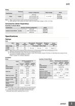
Contact configuration Rated Voltage Note: 1. Relay contact terminals are M5, and the coil terminals are M3.5. 2. When placing an order, specify the model number and rated supply voltage (12 VDC or 24 VDC). Accessories (Order Separately) Auxiliary Contact Block Classification Structure Contact Configuration DPST-NO SPST-NO/SPST-NC Auxiliary Contact Block Specifications Ratings Coil Item Must operate voltage Rated voltage Must release voltage Maximum voltage Percentage of rated voltage 75% max. Note: 1. Rated current and coil resistance were measured at a coil temperature of 23°C with coil resistance...
Open the catalog to page 2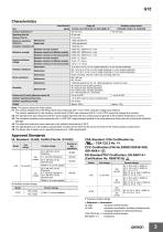
Auxiliary contact block Classification Item Maximum operating frequency Rated load Between coil and contacts 10 kV, 1.2 × 50 µs 4.5 kV, 1.2 × 50 µs 10 to 55 to 10 Hz, 0.5-mm single amplitude (1.0-mm double amplitude) NO: 10 to 55 to 10 Hz, 0.5-mm single amplitude (1.0-mm double amplitude) NC: 10 to 32 to 10 Hz, 0.5-mm single amplitude (1.0-mm double amplitude) Screw mounting: 700 m/s2, DIN Track mounting: 500 m/s2 1,000,000 operations min. (at 1,800 operations/h, contact no load) Between contacts of different polarity Destruction Shock resistance Between contacts of the same polarity Vibration...
Open the catalog to page 3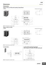
Dimensions Relay (12 VDC, 24 VDC) with Auxiliary Contact Block 4 Poles Mounting Hole Dimensions Two, M4 Note: The dimensions are typical values. Mounting Hole Dimensions Two, M4 Note: The dimensions are typical values. Contact Block Auxiliary DIN Track Mounting Height (when using the PFP-100N or PFP-50N mounting rail) 15 13 47 Note: The dimensions are typical values. Note: The dimensions are typical values.
Open the catalog to page 4
G7Z Terminal Arrangement/Internal Connections Relay with Auxiliary Contact Block G7Z-4A-20Z Note: The coil has no polarity. Note: The coil has no polarity. Note: The coil has no polarity. Note: The coil has no polarity. Note: The coil has no polarity. Note: The coil has no polarity. Note: The coil has no polarity. Note: The coil has no polarity. Note: The coil has no polarity. Auxiliary Contact Block G73Z-20Z 53
Open the catalog to page 5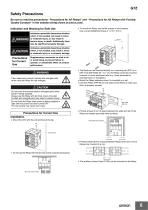
Safety Precautions Be sure to read the precautions “Precautions for All Relays” and “Precautions for All Relays with Forcibly Guided Contacts” in the website at:http://www.ia.omron.com/. Indication and Meaning for Safe Use Indicates a potentially hazardous situation which, if not avoided, will result in minor or moderate injury, or may result in serious injury or death. Additionally there may be significant property damage. • To mount the Relay, secure M4 screws in two locations. Use a screw-tightening torque of 1.2 to 1.3 N·m. Indicates a potentially hazardous situation which, if not avoided,...
Open the catalog to page 6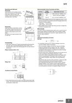
G7Z Mounting and Removal Mounting Recommended Crimp Terminals and Wire Insert the tab on the auxiliary contact block into the groove on the Relay and press down until the hook on the auxiliary contact block catches in the mounting hole on the Relay. Coil section Appropriate wire size • Use the following tightening torque when tightening screws. Loose screws may result in fire caused by abnormal heat generated when the power is being supplied. M5 screws: 2.0 to 2.2 N·m M3.5 screws: 0.8 to 0.9 N·m • Allow suitable slack on leads when wiring, and do not subject the terminals to excessive force....
Open the catalog to page 7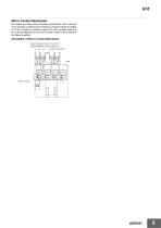
G7Z Mirror Contact Mechanism By combining a Relay with an auxiliary contact block, all NC contacts of the auxiliary contact block will satisfy an impulse withstand voltage of 2.5 kV or higher or maintain a gap of 0.5 mm or greater when the coil is de-energized even if at least one NO contact (main contact) of the Relay is welded. Description of Mirror Contact Mechanism Impulse withstand voltage: 2.5 kV min. or contact separation (a + b): 0.5 mm min. a Auxiliary contact block Contact welding
Open the catalog to page 8
Terms and Conditions Agreement Read and understand this catalog. Please read and understand this catalog before purchasing the products. Please consult your OMRON representative if you have any questions or comments. Warranties. (a) Exclusive Warranty. Omron’s exclusive warranty is that the Products will be free from defects in materials and workmanship for a period of twelve months from the date of sale by Omron (or such other period expressed in writing by Omron). Omron disclaims all other warranties, express or implied. (b) Limitations. OMRON MAKES NO WARRANTY OR REPRESENTATION, EXPRESS OR...
Open the catalog to page 9All OMRON catalogs and technical brochures
 D4F
D4F8 Pages
 D4GS-N
11 Pages
 E4E2
E4E25 Pages
 Fiber SensorBest Selection Catalog
104 Pages
 Fiber Unit E32-LT/LD
4 Pages
 G9SE Series
20 Pages
 NX-SL/SI/SO
20 Pages
 G9SP
G9SP28 Pages
 G9SX-SM
24 Pages
 G9SX-SM/LM
9 Pages
 G9SX/G9SX-GS
49 Pages
 G9SX-LM
28 Pages
 G9SB
G9SB10 Pages
 G9SA
G9SA16 Pages
 DST1 Series
5 Pages
 WS02-CFSC1-E
3 Pages
 G9SA-300-SC
9 Pages
 K8AK-AS
12 Pages
 K8AK-AW
16 Pages
 K8AK-VS
12 Pages
 K8AK-VW
12 Pages
 K8AK-PH
12 Pages
 K8DS-PH
12 Pages
 K8AK-PM
16 Pages
 K8DS-PM
12 Pages
 K8AK-PA
12 Pages
 K8DS-PA
12 Pages
 K8AK-PW
12 Pages
 K8DS-PU
12 Pages
 K8DS-PZ
12 Pages
 K8AK-TS/PT
12 Pages
 K8AK-LS
12 Pages
 K8AK-TH
12 Pages
 K2CM
K2CM16 Pages
 SE
SE15 Pages
 SAO
SAO13 Pages
 APR-S
APR-S6 Pages
 XS5
XS525 Pages
 XS2
XS229 Pages
 F92A
F92A4 Pages
 GLS
GLS3 Pages
 TL-L
TL-L5 Pages
 V680 series
68 Pages
 V680S Series
68 Pages
 MY
MY35 Pages
 E3NC-L/-S
16 Pages
 61F-GPN-BT / -BC
5 Pages
 NE1A-SCPU Series
8 Pages
![NE1A-SCPU0[]-EIP](https://img.directindustry.com/pdf/repository_di/15954/ne1a-scpu0-eip-616667_1mg.jpg) NE1A-SCPU0[]-EIP
NE1A-SCPU0[]-EIP8 Pages
 NE0A-SCPU01
6 Pages
 LY
LY14 Pages
![G2R-[]-S](https://img.directindustry.com/pdf/repository_di/15954/g2r-s-616653_1mg.jpg) G2R-[]-S
G2R-[]-S11 Pages
 G7T
G7T7 Pages
 G2A
G2A9 Pages
 G2A-434
7 Pages
 G2AK
G2AK7 Pages
 MK-S
MK-S9 Pages
 MK-S(X)
12 Pages
 MM
MM17 Pages
 MMK
MMK14 Pages
 G4Q
G4Q6 Pages
 G7J
G7J10 Pages
 E4B
E4B12 Pages
 E4A-3K
9 Pages
 E4C-UDA
5 Pages
 E6H-C
E6H-C5 Pages
 E6F-C
E6F-C5 Pages
 E6D-C
E6D-C5 Pages
 E6B2-C
5 Pages
 E6A2-C
5 Pages
 NL
NL8 Pages
 VB
VB5 Pages
 SC
SC5 Pages
 D5F
D5F5 Pages
 D5A
D5A8 Pages
 E3S-GS3E4
3 Pages
 E3S-R
E3S-R11 Pages
 E3S-A
E3S-A21 Pages
 E3S-CL
9 Pages
 E3ZM-C
14 Pages
 E3T Data Sheet
26 Pages
 E3T Series
6 Pages
 G5 Series
59 Pages
 Sysmac Catalog
410 Pages
 VT-X700
6 Pages
 E5AC-T
8 Pages
 CP1
CP112 Pages
 CP1E
CP1E12 Pages
 MS4800
40 Pages
 VC-DL100
6 Pages
 FZ4 Series
42 Pages
 ZG2
ZG216 Pages
 ZS Series
32 Pages
 ZW Series
24 Pages
 E9NC-T
2 Pages
 Vision System FH series
54 Pages
 CompoNet
28 Pages
 F3SJ Series Safety Light Curtain
108 Pages
 Code Reader/OCR
24 Pages
 Fiber Sensor Best Selection Catalog
100 Pages
 Portable Multi-logger ZR-RX70
12 Pages
 Air Particle Sensor ZN-PD-S
2 Pages
 NT series
18 Pages
 Round Water-resistant Connectors
31 Pages
 Safety Controller G9SP
28 Pages
 E3FA PHOTOELECTRIC SENSORS
24 Pages
 Switch Mode Power Supply S8VK-G
22 Pages
 Data Logger ZR-RX Series
12 Pages
 Programmable Terminals NS Series
57 Pages
 DeviceNet Safety System
30 Pages
 Switching Power Supplies
16 Pages
 Photomicro Sensors
7 Pages
 Displacement Sensors
4 Pages
 R87F / R87T AC Axial Fans
28 Pages
 H8PS Cam Positioner
32 Pages
 OS32C Safety Laser Scanner
24 Pages
 FQ Vision Sensor
17 Pages
 ZN-PD Air Particle Sensor
16 Pages
 S8EX Switch Mode Power Supply
24 Pages
 CP1L CP series CP1L CPU Unit
36 Pages
 E2EF
E2EF8 Pages
 FQ2 Smart camera
24 Pages


Archived catalogs
 REGULATION SOLUTIONS
24 Pages
 Sensor Accessories
38 Pages
 SMART REMOTE I/O
12 Pages
 SAFETY APPLICATION HANDBOOK
55 Pages
 Vision Systems
20 Pages
- SARRALLE industrial robot
- Digital I/O
- Single-pole switch
- IO module
- Propeller fan
- Push-button switch
- SARRALLE air circulation fan
- Digital temperature control
- SARRALLE industrial fan
- Terminal box
- Switching relay
- Analog I/O
- SARRALLE digital indicator
- Digital IO module
- SARRALLE handling robot
- SARRALLE 3D software
- AC fan
- SARRALLE interface software
- SARRALLE panel-mount indicator
- SARRALLE simulation software