G7T
1 /7Pages

G7T
1 /7Pages
Catalog excerpts
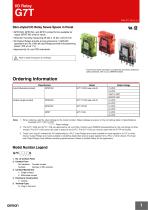
Slim-styled I/O Relay Saves Space in Panel • SPST-NO, SPST-NC, and SPDT contact forms available for output (SPST-NO only for input). • Ultra-slim housing measuring 29 (W) x 10 (D) x 32 (H) mm. • All Output Relays provide a long endurance (1,000,000 operations at 5 A), while all Input Relays provide microswitching power (100 μA at 1 V). • Approved by UL and CSA standards. Refer to Safety Precautions for All Relays. For the most recent information on models that have been certified for safety standards, refer to your OMRON website. Ordering Information Classification Input (bifurcated contact) Output (single contact) Note: 1. When ordering, add the rated voltage to the model number. Rated voltages are given in the coil ratings table in Specifications. Example: G7T-112S 12 VDC Rated voltage 2. The G7T-1122S and G7T-1112S are approved by UL and CSA. Contact your OMRON representative for the coil ratings of other models. The G7T-112S cannot be used in place of the G7TC. The G7T-112S can only be used with the P7TF-05 Socket. 3. “Input” and “output” indicate the I/O relationship to a PLC. Input Relays are mainly suitable for input signals to a PLC or other device. Output Relays are mainly suitable to switching loads that receive output signals from a PLC or other device. The Input and Output Relays have different switching performances. Select a suitable Relay for the application. Model Number Legend G7T-@@@@S 1 1. No. of Contact Poles 2. Contact Form No indication: Transfer contact Number: Number of NO contacts 3. Contact Mechanism 1: Single contact 2: Bifurcated contact 4. Enclosure Construction 2: Casing 5. Terminal Type S: Plug-in Terminal
Open the catalog to page 1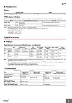
G7T ■ Accessories Socket Applicable Relay P70 Indicator Module Remove the transparent style strip of the Socket and mount this module. It will function as an operation indicator with surge suppression. Model Applicable Relay coil voltage Surge suppressing system with varistor Surge suppressing system with diode Note: 1. Order the Indicator Module that is suited to the Relay coil voltage. 2. The Indicator Module for DC Relays has a multiple power supply common to 12 and 24 VDC. 3. Input current (reference values): 100/110 VAC: 1.14 to 1.38 mA 200/220 VAC: 1.40 to 1.71 mA 12/24 VDC: 4.83 to 5.90...
Open the catalog to page 2
G7T ■ Characteristics Contact resistance (see note 2) Operate time (see note 3) Release time (see note 3) Mechanical:18,000 operations/hour Electrical: 1,800 operations/hour (under rated load) Insulation resistance (see note 4) Dielectric strength Between coil and contacts: 2,000 VAC, 50/60 Hz for 1 minute Between contacts of same polarity: 1,000 VAC, 50/60 Hz for 1 minute Vibration resistance Malfunction: 10 to 55 to 10 Hz, 0.5 mm single amplitude (1.0 mm double amplitude) Shock resistance Mechanical endurance Electrical endurance (see note 5) Input:10,000,000 operations (10 mA) or 50,000 operations...
Open the catalog to page 3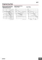
Engineering Data AC inductive load cosφ = 0.4 DC resistive load DC inductive load L/R = 7 ms 24 VDC resistive load 24 VDC inductive load (L/R 7 ms) Input Relay Endurance (x 104 operations) Electrical Endurance Output Relay Endurance (x 104 operations) Maximum Switching Power (Output Model with Life of 1,000,000 Operations) 220 VAC inductive load (cosφ = 0.4)
Open the catalog to page 4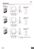
Note: All units are in millimeters unless otherwise indicated. SPST-NO Type SPST-NC Type SPDT Type Terminal Arrangement/ Internal Connections (Bottom View) Terminal Arrangement/ Internal Connections (Bottom View) Terminal Arrangement/ Internal Connections (Bottom View) Note: This Relay cannot be used as an I/O relay terminals and must be used in combination with the exclusive
Open the catalog to page 5
Dimensions Internal Connections (Top View) 19 max. Five, M3.5 × 8 square screws with washers Note: If the I/O SSR or Indicator Module is used, be aware that the polarity of terminal 1 is positive. * We recommend that you insert washers when mounting with M3 screws. A washers are not required when mounting with M4 screws. Indicator Module (with Surge Suppressing Function) P70 Dimensions Internal Connections Safety Precautions Refer to Safety Precautions for All Relays. ALL DIMENSIONS SHOWN ARE IN MILLIMETERS. To convert millimeters into inches, multiply by 0.03937. To convert grams into ounces,...
Open the catalog to page 6
Read and Understand This Catalog Please read and understand this catalog before purchasing the products. Please consult your OMRON representative if you have any questions or comments. Warranty and Limitations of Liability WARRANTY OMRON's exclusive warranty is that the products are free from defects in materials and workmanship for a period of one year (or other period if specified) from date of sale by OMRON. OMRON MAKES NO WARRANTY OR REPRESENTATION, EXPRESS OR IMPLIED, REGARDING NON-INFRINGEMENT, MERCHANTABILITY, OR FITNESS FOR PARTICULAR PURPOSE OF THE PRODUCTS. ANY BUYER OR USER ACKNOWLEDGES...
Open the catalog to page 7All OMRON catalogs and technical brochures
 D4F
D4F8 Pages
 D4GS-N
11 Pages
 E4E2
E4E25 Pages
 Fiber SensorBest Selection Catalog
104 Pages
 Fiber Unit E32-LT/LD
4 Pages
 G9SE Series
20 Pages
 NX-SL/SI/SO
20 Pages
 G9SP
G9SP28 Pages
 G9SX-SM
24 Pages
 G9SX-SM/LM
9 Pages
 G9SX/G9SX-GS
49 Pages
 G9SX-LM
28 Pages
 G9SB
G9SB10 Pages
 G9SA
G9SA16 Pages
 DST1 Series
5 Pages
 WS02-CFSC1-E
3 Pages
 G9SA-300-SC
9 Pages
 K8AK-AS
12 Pages
 K8AK-AW
16 Pages
 K8AK-VS
12 Pages
 K8AK-VW
12 Pages
 K8AK-PH
12 Pages
 K8DS-PH
12 Pages
 K8AK-PM
16 Pages
 K8DS-PM
12 Pages
 K8AK-PA
12 Pages
 K8DS-PA
12 Pages
 K8AK-PW
12 Pages
 K8DS-PU
12 Pages
 K8DS-PZ
12 Pages
 K8AK-TS/PT
12 Pages
 K8AK-LS
12 Pages
 K8AK-TH
12 Pages
 K2CM
K2CM16 Pages
 SE
SE15 Pages
 SAO
SAO13 Pages
 APR-S
APR-S6 Pages
 XS5
XS525 Pages
 XS2
XS229 Pages
 F92A
F92A4 Pages
 GLS
GLS3 Pages
 TL-L
TL-L5 Pages
 V680 series
68 Pages
 V680S Series
68 Pages
 MY
MY35 Pages
 E3NC-L/-S
16 Pages
 61F-GPN-BT / -BC
5 Pages
 NE1A-SCPU Series
8 Pages
![NE1A-SCPU0[]-EIP](https://img.directindustry.com/pdf/repository_di/15954/ne1a-scpu0-eip-616667_1mg.jpg) NE1A-SCPU0[]-EIP
NE1A-SCPU0[]-EIP8 Pages
 NE0A-SCPU01
6 Pages
 LY
LY14 Pages
![G2R-[]-S](https://img.directindustry.com/pdf/repository_di/15954/g2r-s-616653_1mg.jpg) G2R-[]-S
G2R-[]-S11 Pages
 G2A
G2A9 Pages
 G2A-434
7 Pages
 G2AK
G2AK7 Pages
 MK-S
MK-S9 Pages
 MK-S(X)
12 Pages
 MM
MM17 Pages
 MMK
MMK14 Pages
 G4Q
G4Q6 Pages
 G7Z
G7Z9 Pages
 G7J
G7J10 Pages
 E4B
E4B12 Pages
 E4A-3K
9 Pages
 E4C-UDA
5 Pages
 E6H-C
E6H-C5 Pages
 E6F-C
E6F-C5 Pages
 E6D-C
E6D-C5 Pages
 E6B2-C
5 Pages
 E6A2-C
5 Pages
 NL
NL8 Pages
 VB
VB5 Pages
 SC
SC5 Pages
 D5F
D5F5 Pages
 D5A
D5A8 Pages
 E3S-GS3E4
3 Pages
 E3S-R
E3S-R11 Pages
 E3S-A
E3S-A21 Pages
 E3S-CL
9 Pages
 E3ZM-C
14 Pages
 E3T Data Sheet
26 Pages
 E3T Series
6 Pages
 G5 Series
59 Pages
 Sysmac Catalog
410 Pages
 VT-X700
6 Pages
 E5AC-T
8 Pages
 CP1
CP112 Pages
 CP1E
CP1E12 Pages
 MS4800
40 Pages
 VC-DL100
6 Pages
 FZ4 Series
42 Pages
 ZG2
ZG216 Pages
 ZS Series
32 Pages
 ZW Series
24 Pages
 E9NC-T
2 Pages
 Vision System FH series
54 Pages
 CompoNet
28 Pages
 F3SJ Series Safety Light Curtain
108 Pages
 Code Reader/OCR
24 Pages
 Fiber Sensor Best Selection Catalog
100 Pages
 Portable Multi-logger ZR-RX70
12 Pages
 Air Particle Sensor ZN-PD-S
2 Pages
 NT series
18 Pages
 Round Water-resistant Connectors
31 Pages
 Safety Controller G9SP
28 Pages
 E3FA PHOTOELECTRIC SENSORS
24 Pages
 Switch Mode Power Supply S8VK-G
22 Pages
 Data Logger ZR-RX Series
12 Pages
 Programmable Terminals NS Series
57 Pages
 DeviceNet Safety System
30 Pages
 Switching Power Supplies
16 Pages
 Photomicro Sensors
7 Pages
 Displacement Sensors
4 Pages
 R87F / R87T AC Axial Fans
28 Pages
 H8PS Cam Positioner
32 Pages
 OS32C Safety Laser Scanner
24 Pages
 FQ Vision Sensor
17 Pages
 ZN-PD Air Particle Sensor
16 Pages
 S8EX Switch Mode Power Supply
24 Pages
 CP1L CP series CP1L CPU Unit
36 Pages
 E2EF
E2EF8 Pages
 FQ2 Smart camera
24 Pages


Archived catalogs
 REGULATION SOLUTIONS
24 Pages
 Sensor Accessories
38 Pages
 SMART REMOTE I/O
12 Pages
 SAFETY APPLICATION HANDBOOK
55 Pages
 Vision Systems
20 Pages
- SARRALLE industrial robot
- Digital I/O
- Single-pole switch
- IO module
- Propeller fan
- Push-button switch
- SARRALLE air circulation fan
- Digital temperature control
- SARRALLE industrial fan
- Terminal box
- Switching relay
- Analog I/O
- SARRALLE digital indicator
- Digital IO module
- SARRALLE handling robot
- SARRALLE 3D software
- AC fan
- SARRALLE interface software
- SARRALLE panel-mount indicator
- SARRALLE simulation software