G2A-434
1 /7Pages

G2A-434
1 /7Pages
Catalog excerpts
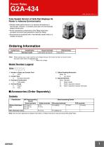
Power Relay Fully Sealed Version of G2A that Displays Its Power in Adverse Environments • Exhibits stable performance in an adverse atmosphere of harmful gas, moisture, or powdery dust due to its hermetically sealed construction. • All the mechanical components of the Relay have been annealed to prevent gas generation inside the Relay. • Economical as compared with a hermetically sealed relay in a metallic enclosure. Ordering Information Contact form 4PDT Classification Standard model Note: When placing your order, add the coil voltage rating to the model number as shown below. Example: G2A-434A-VS 200/220 VAC Rated coil voltage Model Number Legend G2A-@@@@@-@ 1 5. Safety Breaking Mechanism None: No Y: Arc barrier 6. Special Elements None: Standard D: Built-in diode N: Built-in operation indicator N1: Built-in operation indicator and diode 1. Number of Poles and Contact Form 4: 4PDT 2. Contact Type 3: Crossbar bifurcated 3. Enclosure Construction 4: Fully sealed 4. Terminal Shape A: Plug-in 1P: PCB ■ Accessories (Order Separately) Sockets Classification DIN Track-mounting Socket Screw terminals Without Hold-down Clip With Hold-down Clip --- Back-connecting Socket Solder terminals Wire-wrap terminals Note: See the G2A datasheet for detailed information on Relay Hold-down Clips and Socket Mounting Plates.
Open the catalog to page 1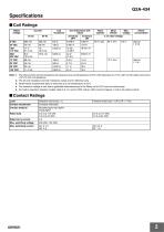
Specifications ■ Coil Ratings Rated voltage Coil inductance (ref. value) Armature OFF Must operate Power consumption Must release Note: 1. The rated current and coil resistance are measured at a coil temperature of 23°C with tolerances of +15%/–20% for AC rated current and ±15% for DC coil resistance. 2. The AC coil resistance and coil inductance values are for reference only. 3. Performance characteristic data is measured at a coil temperature of 23°C. 4. The maximum voltage is one that is applicable instantaneously to the Relay coil at 23°C and not continuously. 5. For built-in operation indicator...
Open the catalog to page 2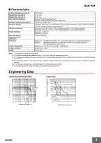
G2A-434 ■ Characteristics Contact resistance (see note 2) Operate time (see note 3) Release time (see note 3) Mechanical: 18,000 operations/hour Electrical: 1,800 operations/hour (under rated load) Insulation resistance (see note 4) Dielectric strength 1,500 VAC, 50/60 Hz for 1 minute between coil and contact and between contacts of different polarities (700 VAC between contacts of same polarities) Vibration resistance Destruction: 10 to 55 to 10 Hz, 0.75 mm single amplitude (1.5 mm double amplitude) Malfunction: 10 to 55 to 10 Hz, 0.5 mm single amplitude (1.0 mm double amplitude) Shock resistance...
Open the catalog to page 3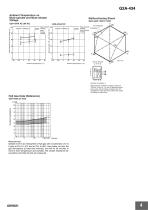
G2A-434 Ambient Temperature vs. Must-operate and Must-release Voltage G2A-434A DC Must-operate voltage Mustrelease voltage Must-operate and reset voltage (%) Must-operate and reset voltage (%) Not energized Must-operate Energized voltage Must-release voltage Shock direction Ambient temperature (°C) Number of samples: 5 Measurement conditions: Impose a shock of 100 m/s2 in the ±X, ±Y, and ±Z directions three times each with the Relay energized and not energized to check the shock values that cause the Relay to malfunction. Contact resistance Hours Measurement: Sample is left in an atmosphere of...
Open the catalog to page 4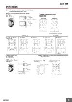
Note: 1. All units are in millimeters unless otherwise indicated. Plug-in Terminal/Solder Terminal Model s Fourteen, 1.2-dia. holes x 3 elliptic holes Terminal Arrangement/Internal (Bottom View) Be sure to wire the terminals with the correct polarity. Operation indicator color Note: DC models have coil polarity. Be sure to wire the terminals with (Bottom View) Terminal Arrangement (Bottom View)
Open the catalog to page 5
Safety Precautions Refer to Safety precautions for All Relays. DC models with a built-in indicator or built-in diode have coil polarity. Be sure to wire the terminals with the correct polarity. ALL DIMENSIONS SHOWN ARE IN MILLIMETERS. To convert millimeters into inches, multiply by 0.03937. To convert grams into ounces, multiply by 0.03527. In the interest of product improvement, specifications are subject to change without notice.
Open the catalog to page 6
Read and Understand This Catalog Please read and understand this catalog before purchasing the products. Please consult your OMRON representative if you have any questions or comments. Warranty and Limitations of Liability WARRANTY OMRON's exclusive warranty is that the products are free from defects in materials and workmanship for a period of one year (or other period if specified) from date of sale by OMRON. OMRON MAKES NO WARRANTY OR REPRESENTATION, EXPRESS OR IMPLIED, REGARDING NON-INFRINGEMENT, MERCHANTABILITY, OR FITNESS FOR PARTICULAR PURPOSE OF THE PRODUCTS. ANY BUYER OR USER ACKNOWLEDGES...
Open the catalog to page 7All OMRON catalogs and technical brochures
 D4F
D4F8 Pages
 D4GS-N
11 Pages
 E4E2
E4E25 Pages
 Fiber SensorBest Selection Catalog
104 Pages
 Fiber Unit E32-LT/LD
4 Pages
 G9SE Series
20 Pages
 NX-SL/SI/SO
20 Pages
 G9SP
G9SP28 Pages
 G9SX-SM
24 Pages
 G9SX-SM/LM
9 Pages
 G9SX/G9SX-GS
49 Pages
 G9SX-LM
28 Pages
 G9SB
G9SB10 Pages
 G9SA
G9SA16 Pages
 DST1 Series
5 Pages
 WS02-CFSC1-E
3 Pages
 G9SA-300-SC
9 Pages
 K8AK-AS
12 Pages
 K8AK-AW
16 Pages
 K8AK-VS
12 Pages
 K8AK-VW
12 Pages
 K8AK-PH
12 Pages
 K8DS-PH
12 Pages
 K8AK-PM
16 Pages
 K8DS-PM
12 Pages
 K8AK-PA
12 Pages
 K8DS-PA
12 Pages
 K8AK-PW
12 Pages
 K8DS-PU
12 Pages
 K8DS-PZ
12 Pages
 K8AK-TS/PT
12 Pages
 K8AK-LS
12 Pages
 K8AK-TH
12 Pages
 K2CM
K2CM16 Pages
 SE
SE15 Pages
 SAO
SAO13 Pages
 APR-S
APR-S6 Pages
 XS5
XS525 Pages
 XS2
XS229 Pages
 F92A
F92A4 Pages
 GLS
GLS3 Pages
 TL-L
TL-L5 Pages
 V680 series
68 Pages
 V680S Series
68 Pages
 MY
MY35 Pages
 E3NC-L/-S
16 Pages
 61F-GPN-BT / -BC
5 Pages
 NE1A-SCPU Series
8 Pages
![NE1A-SCPU0[]-EIP](https://img.directindustry.com/pdf/repository_di/15954/ne1a-scpu0-eip-616667_1mg.jpg) NE1A-SCPU0[]-EIP
NE1A-SCPU0[]-EIP8 Pages
 NE0A-SCPU01
6 Pages
 LY
LY14 Pages
![G2R-[]-S](https://img.directindustry.com/pdf/repository_di/15954/g2r-s-616653_1mg.jpg) G2R-[]-S
G2R-[]-S11 Pages
 G7T
G7T7 Pages
 G2A
G2A9 Pages
 G2AK
G2AK7 Pages
 MK-S
MK-S9 Pages
 MK-S(X)
12 Pages
 MM
MM17 Pages
 MMK
MMK14 Pages
 G4Q
G4Q6 Pages
 G7Z
G7Z9 Pages
 G7J
G7J10 Pages
 E4B
E4B12 Pages
 E4A-3K
9 Pages
 E4C-UDA
5 Pages
 E6H-C
E6H-C5 Pages
 E6F-C
E6F-C5 Pages
 E6D-C
E6D-C5 Pages
 E6B2-C
5 Pages
 E6A2-C
5 Pages
 NL
NL8 Pages
 VB
VB5 Pages
 SC
SC5 Pages
 D5F
D5F5 Pages
 D5A
D5A8 Pages
 E3S-GS3E4
3 Pages
 E3S-R
E3S-R11 Pages
 E3S-A
E3S-A21 Pages
 E3S-CL
9 Pages
 E3ZM-C
14 Pages
 E3T Data Sheet
26 Pages
 E3T Series
6 Pages
 G5 Series
59 Pages
 Sysmac Catalog
410 Pages
 VT-X700
6 Pages
 E5AC-T
8 Pages
 CP1
CP112 Pages
 CP1E
CP1E12 Pages
 MS4800
40 Pages
 VC-DL100
6 Pages
 FZ4 Series
42 Pages
 ZG2
ZG216 Pages
 ZS Series
32 Pages
 ZW Series
24 Pages
 E9NC-T
2 Pages
 Vision System FH series
54 Pages
 CompoNet
28 Pages
 F3SJ Series Safety Light Curtain
108 Pages
 Code Reader/OCR
24 Pages
 Fiber Sensor Best Selection Catalog
100 Pages
 Portable Multi-logger ZR-RX70
12 Pages
 Air Particle Sensor ZN-PD-S
2 Pages
 NT series
18 Pages
 Round Water-resistant Connectors
31 Pages
 Safety Controller G9SP
28 Pages
 E3FA PHOTOELECTRIC SENSORS
24 Pages
 Switch Mode Power Supply S8VK-G
22 Pages
 Data Logger ZR-RX Series
12 Pages
 Programmable Terminals NS Series
57 Pages
 DeviceNet Safety System
30 Pages
 Switching Power Supplies
16 Pages
 Photomicro Sensors
7 Pages
 Displacement Sensors
4 Pages
 R87F / R87T AC Axial Fans
28 Pages
 H8PS Cam Positioner
32 Pages
 OS32C Safety Laser Scanner
24 Pages
 FQ Vision Sensor
17 Pages
 ZN-PD Air Particle Sensor
16 Pages
 S8EX Switch Mode Power Supply
24 Pages
 CP1L CP series CP1L CPU Unit
36 Pages
 E2EF
E2EF8 Pages
 FQ2 Smart camera
24 Pages


Archived catalogs
 REGULATION SOLUTIONS
24 Pages
 Sensor Accessories
38 Pages
 SMART REMOTE I/O
12 Pages
 SAFETY APPLICATION HANDBOOK
55 Pages
 Vision Systems
20 Pages
- SARRALLE industrial robot
- Digital I/O
- Single-pole switch
- IO module
- Propeller fan
- Push-button switch
- SARRALLE air circulation fan
- Digital temperature control
- SARRALLE industrial fan
- Terminal box
- Switching relay
- Analog I/O
- SARRALLE digital indicator
- Digital IO module
- SARRALLE handling robot
- SARRALLE 3D software
- AC fan
- SARRALLE interface software
- SARRALLE panel-mount indicator
- SARRALLE simulation software