E3S-A
1 /21Pages

E3S-A
1 /21Pages
Catalog excerpts
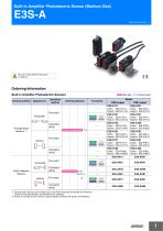
Built-in Amplifier Photoelectric Sensor (Medium Size) Be sure to read Safety Precautions on page 10. Ordering Information Built-in Amplifier Photoelectric Sensors Sensing method Connection method Sensing distance Self Diagnosis External Diagnosis Emitter E3S-AT21-L Receiver E3S-AT21-D Emitter E3S-AT16-L Receiver E3S-AT16-D Turbo External Diagnosis Timer Self Diagnosis NPN output E3S-AT11 Emitter E3S-AT11-L Receiver E3S-AT11-D Infrared light Turbo External Diagnosis Self Diagnosis Horizontal Retro-reflective Sensors Self Diagnosis External Diagnosis *1. Through-beam Sensors are normally sold in sets that include both the Emitter and Receiver. Orders for individual Emitters and Receivers are accepted. *2. Values in brackets are the minimum required distance between the Sensor and Reflector.
Open the catalog to page 1
Sensing method Connection method Sensing distance Self Diagnosis 100 mm (wide view) Connector (M12) Timer Self Diagnosis Self Diagnosis Self Diagnosis Diffuse-reflective Sensors Self Diagnosis Self Diagnosis Model NPN output PNP output E3S-AD13 *3 E3S-AD33 *3. The following models are available with 200-mm sensing distances: E3S-AD14 and E3S-AD64. Accessories (Order Separately) Insert-type Long Slit Slit width Sensing distance Minimum sensing object (typical) 0.2-mm dia. 0.4-mm dia. 1 of each for Emitter/ Receiver (4 Slits total) 1 of each for Emitter/ Receiver (2 Slits total) Remarks Slits can...
Open the catalog to page 2
E3S-A Mounting Brackets/Other Appearance Provided with E3S-A Horizontal Sensors. Provided with E3S-A Vertical Sensors. Provided with E3S-A Vertical Pre-wired Sensors. Provided with E3S-A Vertical Connector Sensors. Protective Cover for Horizontal Sensors Note: When mounting Sensors with Connectors, the Sensor I/O Connector will come into contact with the Bracket. Mount the Sensor with care. Protective Cover for Vertical Sensors Note: Cannot be used with Sensors with Connectors. Close Mounting Plate: Provided with E3S-A Connector Sensors. Note: If a Through-beam Model is used, order two Mounting...
Open the catalog to page 3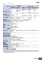
E3S-A Ratings and Specifications Retro-reflective Sensors (with MSR function) Through-beam Sensors Sensing method Diffuse-reflective Sensors 100 mm (wide view) (white paper 100 × 100 mm) Sensing distance Standard sensing object Differential travel Directional angle Both Emitter and Receiver: 3° to 15° Light source (wavelength) Power supply voltage Current consumption Both Emitter and Receiver: 20 mA max. (plus approx. 15 mA with turbo function) Control output Load power supply voltage: 30 VDC max., Load current: 100 mA max. (residual voltage: 1 V max.) Open-collector output (NPN or PNP depending...
Open the catalog to page 4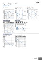
E3S-A Engineering Data (Reference Value) Parallel Sensing Range Through-beam Sensors E3S-AT@@ + E39-S46 (Slit Sold Separately) E3S-AT@@ + E39-E6 (Filter Sold Separately) Through-beam Sensors Through-beam Sensors Slit width: 2 mm Y Slit width: 1 mm X Diffuse-reflective Sensors Sensing Range Retro-reflective Sensors Parallel Sensing Range Sensing object: white paper E3S-AD@1/@3/@6/@8: 100 × 100 mm E3S-AD@2/@7: 200 × 200 mm Excess Gain vs. Set Distance Retro-reflective Sensors Excess gain ratio (times) Excess gain ratio (times) Through-beam Sensors
Open the catalog to page 5
E3S-AD@1/AD@2/AD@3/AD@6/AD@7/ AD@8 (Detection of White Paper) E3S-AD@1/AD@2/AD@3/AD@6/AD@7/ AD@8 (Detection of Black Paper) Sensing object: Black paper E3S-AD@1/@3/@6/@8: 100 × 100 mm E3S-AD@2/@7: 200 × 200 mm Sensing object: white paper OFF ON Sensing Object Size vs. Sensing Distance Excess gain ratio (times) Diffuse-reflective Sensor Excess gain ratio (times) Diffuse-reflective Sensor I/O Circuit Diagrams NPN Output Model E3S-AT11 * E3S-AT16 * E3S-AT61 * E3S-AT66 * Operation mode Timing charts Incident light No incident light Light indicator ON (red) OFF ON Output transistor OFF Operate Load...
Open the catalog to page 6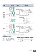
Operation mode Mode selector switch Timing charts Through-beam Receivers, Diffuse-reflective Sensors Incident light No incident light Light indicator ON (red) OFF Output transistor Output circuit Operate Load (e.g., relay) Reset (Between brown and black) T: OFF-delay timer (0 to 100 ms) Stability indicator (green) Load (relay) 100 mA max. Photoelectric Sensor main circuit Incident light No incident light Orange (Self-diagnostic output) Load Black (Control (relay) output) T ON OFF Operate Load (e.g., relay) Reset (Between brown and black) T: OFF-delay timer (0 to 100 ms) Output transistor Through-beam...
Open the catalog to page 7
Operation mode ON Output transistor OFF Operate Load (e.g., relay) Reset (Between blue and black) Stability indicator (green) Photoelectric Sensor main circuit Black (Control output) 4 Incident light No incident light Output transistor Load (Relay) OFF Operate Load (e.g., relay) Reset (Between blue and black) Through-beam Model Emitters Connector Pin Arrangement Light indicator Photo(red) electric Sensor main circuit Incident light No incident light T Light indicator ON (red) OFF ON Output transistor OFF Operate Load (e.g., relay) Reset (Between blue and black) T: OFF-delay timer (0 to 100 ms)...
Open the catalog to page 8
Operation mode Mode selector switch Timing charts Output circuit Retro-reflective Sensors Incident light No incident light T ON OFF Operate Load (e.g., relay) Reset (Between blue and black) T: OFF-delay timer (0 to 100 ms) Output transistor L Side (LIGHT ON) Light indicator Stability indicator (green) Photoelectric Sensor main circuit Incident light No incident light Light indicator ON (red) OFF Output transistor (External diagnostic input) (Self-diagnostic Orange output) (Control output) Load Black (relay) Load (relay) Operate Load (e.g., relay) Reset (Between brown and black) T: OFF-delay timer...
Open the catalog to page 9
E3S-A Safety Precautions WARNING This product is not designed or rated for ensuring safety of persons. Do not use it for such purposes. Precautions for Correct Use Do not use the product in atmospheres or environments that exceed product ratings. Mounting Position of Optical Axis of Through-beam Model Unlike conventional through-beam sensors, the E3S-A Through-beam Photoelectric Sensor incorporates 2 lenses. The lens actually in use is the one marked with an arrow indicating the position of the optical axis. When using a Slit, attach it to the lens marked with the arrow. Mounting Bracket (Provided)...
Open the catalog to page 10All OMRON catalogs and technical brochures
 D4F
D4F8 Pages
 D4GS-N
11 Pages
 E4E2
E4E25 Pages
 Fiber SensorBest Selection Catalog
104 Pages
 Fiber Unit E32-LT/LD
4 Pages
 G9SE Series
20 Pages
 NX-SL/SI/SO
20 Pages
 G9SP
G9SP28 Pages
 G9SX-SM
24 Pages
 G9SX-SM/LM
9 Pages
 G9SX/G9SX-GS
49 Pages
 G9SX-LM
28 Pages
 G9SB
G9SB10 Pages
 G9SA
G9SA16 Pages
 DST1 Series
5 Pages
 WS02-CFSC1-E
3 Pages
 G9SA-300-SC
9 Pages
 K8AK-AS
12 Pages
 K8AK-AW
16 Pages
 K8AK-VS
12 Pages
 K8AK-VW
12 Pages
 K8AK-PH
12 Pages
 K8DS-PH
12 Pages
 K8AK-PM
16 Pages
 K8DS-PM
12 Pages
 K8AK-PA
12 Pages
 K8DS-PA
12 Pages
 K8AK-PW
12 Pages
 K8DS-PU
12 Pages
 K8DS-PZ
12 Pages
 K8AK-TS/PT
12 Pages
 K8AK-LS
12 Pages
 K8AK-TH
12 Pages
 K2CM
K2CM16 Pages
 SE
SE15 Pages
 SAO
SAO13 Pages
 APR-S
APR-S6 Pages
 XS5
XS525 Pages
 XS2
XS229 Pages
 F92A
F92A4 Pages
 GLS
GLS3 Pages
 TL-L
TL-L5 Pages
 V680 series
68 Pages
 V680S Series
68 Pages
 MY
MY35 Pages
 E3NC-L/-S
16 Pages
 61F-GPN-BT / -BC
5 Pages
 NE1A-SCPU Series
8 Pages
![NE1A-SCPU0[]-EIP](https://img.directindustry.com/pdf/repository_di/15954/ne1a-scpu0-eip-616667_1mg.jpg) NE1A-SCPU0[]-EIP
NE1A-SCPU0[]-EIP8 Pages
 NE0A-SCPU01
6 Pages
 LY
LY14 Pages
![G2R-[]-S](https://img.directindustry.com/pdf/repository_di/15954/g2r-s-616653_1mg.jpg) G2R-[]-S
G2R-[]-S11 Pages
 G7T
G7T7 Pages
 G2A
G2A9 Pages
 G2A-434
7 Pages
 G2AK
G2AK7 Pages
 MK-S
MK-S9 Pages
 MK-S(X)
12 Pages
 MM
MM17 Pages
 MMK
MMK14 Pages
 G4Q
G4Q6 Pages
 G7Z
G7Z9 Pages
 G7J
G7J10 Pages
 E4B
E4B12 Pages
 E4A-3K
9 Pages
 E4C-UDA
5 Pages
 E6H-C
E6H-C5 Pages
 E6F-C
E6F-C5 Pages
 E6D-C
E6D-C5 Pages
 E6B2-C
5 Pages
 E6A2-C
5 Pages
 NL
NL8 Pages
 VB
VB5 Pages
 SC
SC5 Pages
 D5F
D5F5 Pages
 D5A
D5A8 Pages
 E3S-GS3E4
3 Pages
 E3S-R
E3S-R11 Pages
 E3S-CL
9 Pages
 E3ZM-C
14 Pages
 E3T Data Sheet
26 Pages
 E3T Series
6 Pages
 G5 Series
59 Pages
 Sysmac Catalog
410 Pages
 VT-X700
6 Pages
 E5AC-T
8 Pages
 CP1
CP112 Pages
 CP1E
CP1E12 Pages
 MS4800
40 Pages
 VC-DL100
6 Pages
 FZ4 Series
42 Pages
 ZG2
ZG216 Pages
 ZS Series
32 Pages
 ZW Series
24 Pages
 E9NC-T
2 Pages
 Vision System FH series
54 Pages
 CompoNet
28 Pages
 F3SJ Series Safety Light Curtain
108 Pages
 Code Reader/OCR
24 Pages
 Fiber Sensor Best Selection Catalog
100 Pages
 Portable Multi-logger ZR-RX70
12 Pages
 Air Particle Sensor ZN-PD-S
2 Pages
 NT series
18 Pages
 Round Water-resistant Connectors
31 Pages
 Safety Controller G9SP
28 Pages
 E3FA PHOTOELECTRIC SENSORS
24 Pages
 Switch Mode Power Supply S8VK-G
22 Pages
 Data Logger ZR-RX Series
12 Pages
 Programmable Terminals NS Series
57 Pages
 DeviceNet Safety System
30 Pages
 Switching Power Supplies
16 Pages
 Photomicro Sensors
7 Pages
 Displacement Sensors
4 Pages
 R87F / R87T AC Axial Fans
28 Pages
 H8PS Cam Positioner
32 Pages
 OS32C Safety Laser Scanner
24 Pages
 FQ Vision Sensor
17 Pages
 ZN-PD Air Particle Sensor
16 Pages
 S8EX Switch Mode Power Supply
24 Pages
 CP1L CP series CP1L CPU Unit
36 Pages
 E2EF
E2EF8 Pages
 FQ2 Smart camera
24 Pages


Archived catalogs
 REGULATION SOLUTIONS
24 Pages
 Sensor Accessories
38 Pages
 SMART REMOTE I/O
12 Pages
 SAFETY APPLICATION HANDBOOK
55 Pages
 Vision Systems
20 Pages
- SARRALLE industrial robot
- Digital I/O
- Single-pole switch
- IO module
- Propeller fan
- Push-button switch
- SARRALLE air circulation fan
- Digital temperature control
- SARRALLE industrial fan
- Terminal box
- Switching relay
- Analog I/O
- SARRALLE digital indicator
- Digital IO module
- SARRALLE handling robot
- SARRALLE 3D software
- AC fan
- SARRALLE interface software
- SARRALLE panel-mount indicator
- SARRALLE simulation software