D4GS-N
1 /11Pages

D4GS-N
1 /11Pages
Catalog excerpts

Slim Safety Door Switches with IP67 Rating • Slim design with a width of only 17 mm (three-contact models). • Reversible design allowing either front or rear mounting. • Built-in Switches with two- or three-terminal contact construction are available. • Operation Key with rubber mounting hole to absorb vibration and shock. • IP67 degree of protection. A Be sure to read the “Safety Precautions”on page 9. Model Number Legend Switch D4GS-NDQ-P 1 2 3 3. Cable Length Blank: 1 m 3: 3 m 1. Operation Key Type 1: Horizontal mounting 2: Vertical mounting 4: Adjustable mounting (Vertical upward) 4-2: Adjustable mounting (Vertical downward) 2. Direction of Operation Key Insertion R: Horizontal T: Vertical Ordering Information List of Models Switches (Operation Keys are sold separately.) Consult with your OMRON representative when ordering any models that are not listed in this table.
Open the catalog to page 1
Specifications Certified Standards Certification body * Certification for CSA C22.2 No. 14 is authorized by the UL mark. Standards and EC Directives Conforms to the following EC Directives: • Machinery Directive • Low Voltage Directive • EN ISO 14119 • EN60204-1 • GS-ET-15 TUV (EN60947-5-1), CCC (GB/T 14048.5) Item Utilization category Note: Use a 10 A fuse type gI or gG that conforms to IEC60269 as a short-circuit protection device.
Open the catalog to page 2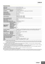
Note: 1. The above values are initial values. 2. The Switch contacts can be used with either standard loads or microloads. Once the contacts have been used to switch a load, however, they cannot be used to switch smaller loads. The contact surfaces will become rough once they have been used and contact reliability for smaller loads may be reduced. *1. The degree of protection shown above is based on the test method specified in EN60947-5-1. Be sure to confirm in advance the sealing performance under the actual operating environment and conditions. Although the switch box is protected from dust,...
Open the catalog to page 3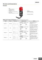
Structure and NomenclatureStructure Model and Contact Configuration (Diagrams Show State with Key Inserted. Model Contact form Operating pattern Operation Key insertion completion position Extraction completion position Only NC contact 11-12 has a certified direct opening mechanism. The terminals 11-12 and 33-34 can be used as unlike poles. Operation Key insertion completion position Extraction completion position NC contacts 11-12 and 31-32 have a certified direct opening mechanism. The terminals 11-12 and 31-32 can be used as unlike poles. Operation Key insertion completion position Extraction...
Open the catalog to page 4
Dimensions and Operating Characteristics (Operation Key center position) Key insertion force Key extraction force Movement before being locked Red 8.4 (Operation Key center position) Black 2.15±0.05R mounting hole: Note: 1. Unless otherwise specified, a tolerance of ±0.4 mm applies to all dimensions. Dimensions in parentheses are reference values. 2. There are fluctuations in the contact ON/OFF timing for Switches with multiple poles (2NC, 2NC/1NO, or 3NC). Confirm performance before application.
Open the catalog to page 5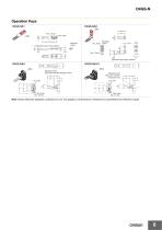
1.4 (Operation Key center position) Mounting rubber Two, 4.3 dia. 12.6 (Operation Key center position) Black Adjusting screw (Set screw with M4 hexagonal hole) Adjusting screw (Set screw with M4 hexagonal hole) Note: Unless otherwise specified, a tolerance of ±0.4 mm applies to all dimensions. Dimensions in parentheses are reference values.
Open the catalog to page 6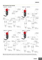
D4GS-N With Operation Key Inserted D4GS-N@T-@ + D4GS-NK1 D4GS-N@R-@ + D4GS-NK1 Operation key insertion radius (R ≥ 170) *9 Operation key insertion radius (R ≥ 170) *9 Black Black 13.5 to 16 Operation key insertion position 13.5 to 16 Operation key insertion position 13.5 to 16 Operation key insertion position 13.5 to 16 Operation key insertion position Operation key insertion face Operation key insertion radius (R ≥ 160) *9 (12.3±1) *3 Operation key Operation insertion radius key (R ≥ 160) *9 insertion face Operation key insertion face 13.5 to 16 Operation key insertion position Operation key...
Open the catalog to page 7
21.5 to 24 Operation key insertion position Operation key insertion radius (R ≥ 50) * Adjusting screw Note 1: When determining the operation key insertion radius, adjust the adjusting screw so that the tip of the operation key is positioned to the center of the key insertion hole of the Switch. Operation key insertion radius (R ≥ 50) * 21.5 to 24 Operation key insertion position Note 2: The operation key cannot be inserted or adjusted in a direction different from the one shown above. Use the D4GS-NK1 or D4GS-NK2 if necessary. Note 1: When determining the operation key insertion radius, adjust...
Open the catalog to page 8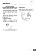
Safety Precautions Be sure to read the precautions for All Safety Door Switches in the website at:http://www.ia.omron.com/. Precautions for Safe Use Supplementary comments on what to do or avoid doing, to use the product safely. • Do not use the Switch submersed in oil or water or in locations continuously subject to splashes of oil or water. Doing so may result in oil or water entering the Switch. (The IP67 degree of protection of the Switch specifies the amount of water penetration after the Switch is submerged in water for a certain period of time.) • Although the Switch body is protected...
Open the catalog to page 9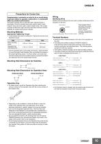
Cross section ^ \ Dummy insulator (black) External insulation sheath Supplementary comments on what to do or avoid doing, to prevent failure to operate, malfunction or undesirable effect on product performance. The Switch contacts can be used with either standard loads or microloads. Once the contacts have been used to switch a load, however, they cannot be used to switch smaller loads. The contact surfaces will become rough once they have been used and contact reliability for smaller loads may be reduced. Mounting Methods Appropriate Tightening Torque • Loose screws may result in malfunction....
Open the catalog to page 10
Terms and Conditions Agreement Read and understand this catalog. Please read and understand this catalog before purchasing the products. Please consult your OMRON representative if you have any questions or comments. Warranties. (a) Exclusive Warranty. Omron’s exclusive warranty is that the Products will be free from defects in materials and workmanship for a period of twelve months from the date of sale by Omron (or such other period expressed in writing by Omron). Omron disclaims all other warranties, express or implied. (b) Limitations. OMRON MAKES NO WARRANTY OR REPRESENTATION, EXPRESS OR...
Open the catalog to page 11All OMRON catalogs and technical brochures
 D4F
D4F8 Pages
 E4E2
E4E25 Pages
 Fiber SensorBest Selection Catalog
104 Pages
 Fiber Unit E32-LT/LD
4 Pages
 G9SE Series
20 Pages
 NX-SL/SI/SO
20 Pages
 G9SP
G9SP28 Pages
 G9SX-SM
24 Pages
 G9SX-SM/LM
9 Pages
 G9SX/G9SX-GS
49 Pages
 G9SX-LM
28 Pages
 G9SB
G9SB10 Pages
 G9SA
G9SA16 Pages
 DST1 Series
5 Pages
 WS02-CFSC1-E
3 Pages
 G9SA-300-SC
9 Pages
 K8AK-AS
12 Pages
 K8AK-AW
16 Pages
 K8AK-VS
12 Pages
 K8AK-VW
12 Pages
 K8AK-PH
12 Pages
 K8DS-PH
12 Pages
 K8AK-PM
16 Pages
 K8DS-PM
12 Pages
 K8AK-PA
12 Pages
 K8DS-PA
12 Pages
 K8AK-PW
12 Pages
 K8DS-PU
12 Pages
 K8DS-PZ
12 Pages
 K8AK-TS/PT
12 Pages
 K8AK-LS
12 Pages
 K8AK-TH
12 Pages
 K2CM
K2CM16 Pages
 SE
SE15 Pages
 SAO
SAO13 Pages
 APR-S
APR-S6 Pages
 XS5
XS525 Pages
 XS2
XS229 Pages
 F92A
F92A4 Pages
 GLS
GLS3 Pages
 TL-L
TL-L5 Pages
 V680 series
68 Pages
 V680S Series
68 Pages
 MY
MY35 Pages
 E3NC-L/-S
16 Pages
 61F-GPN-BT / -BC
5 Pages
 NE1A-SCPU Series
8 Pages
![NE1A-SCPU0[]-EIP](https://img.directindustry.com/pdf/repository_di/15954/ne1a-scpu0-eip-616667_1mg.jpg) NE1A-SCPU0[]-EIP
NE1A-SCPU0[]-EIP8 Pages
 NE0A-SCPU01
6 Pages
 LY
LY14 Pages
![G2R-[]-S](https://img.directindustry.com/pdf/repository_di/15954/g2r-s-616653_1mg.jpg) G2R-[]-S
G2R-[]-S11 Pages
 G7T
G7T7 Pages
 G2A
G2A9 Pages
 G2A-434
7 Pages
 G2AK
G2AK7 Pages
 MK-S
MK-S9 Pages
 MK-S(X)
12 Pages
 MM
MM17 Pages
 MMK
MMK14 Pages
 G4Q
G4Q6 Pages
 G7Z
G7Z9 Pages
 G7J
G7J10 Pages
 E4B
E4B12 Pages
 E4A-3K
9 Pages
 E4C-UDA
5 Pages
 E6H-C
E6H-C5 Pages
 E6F-C
E6F-C5 Pages
 E6D-C
E6D-C5 Pages
 E6B2-C
5 Pages
 E6A2-C
5 Pages
 NL
NL8 Pages
 VB
VB5 Pages
 SC
SC5 Pages
 D5F
D5F5 Pages
 D5A
D5A8 Pages
 E3S-GS3E4
3 Pages
 E3S-R
E3S-R11 Pages
 E3S-A
E3S-A21 Pages
 E3S-CL
9 Pages
 E3ZM-C
14 Pages
 E3T Data Sheet
26 Pages
 E3T Series
6 Pages
 G5 Series
59 Pages
 Sysmac Catalog
410 Pages
 VT-X700
6 Pages
 E5AC-T
8 Pages
 CP1
CP112 Pages
 CP1E
CP1E12 Pages
 MS4800
40 Pages
 VC-DL100
6 Pages
 FZ4 Series
42 Pages
 ZG2
ZG216 Pages
 ZS Series
32 Pages
 ZW Series
24 Pages
 E9NC-T
2 Pages
 Vision System FH series
54 Pages
 CompoNet
28 Pages
 F3SJ Series Safety Light Curtain
108 Pages
 Code Reader/OCR
24 Pages
 Fiber Sensor Best Selection Catalog
100 Pages
 Portable Multi-logger ZR-RX70
12 Pages
 Air Particle Sensor ZN-PD-S
2 Pages
 NT series
18 Pages
 Round Water-resistant Connectors
31 Pages
 Safety Controller G9SP
28 Pages
 E3FA PHOTOELECTRIC SENSORS
24 Pages
 Switch Mode Power Supply S8VK-G
22 Pages
 Data Logger ZR-RX Series
12 Pages
 Programmable Terminals NS Series
57 Pages
 DeviceNet Safety System
30 Pages
 Switching Power Supplies
16 Pages
 Photomicro Sensors
7 Pages
 Displacement Sensors
4 Pages
 R87F / R87T AC Axial Fans
28 Pages
 H8PS Cam Positioner
32 Pages
 OS32C Safety Laser Scanner
24 Pages
 FQ Vision Sensor
17 Pages
 ZN-PD Air Particle Sensor
16 Pages
 S8EX Switch Mode Power Supply
24 Pages
 CP1L CP series CP1L CPU Unit
36 Pages
 E2EF
E2EF8 Pages
 FQ2 Smart camera
24 Pages


Archived catalogs
 REGULATION SOLUTIONS
24 Pages
 Sensor Accessories
38 Pages
 SMART REMOTE I/O
12 Pages
 SAFETY APPLICATION HANDBOOK
55 Pages
 Vision Systems
20 Pages
- SARRALLE industrial robot
- Digital I/O
- Single-pole switch
- IO module
- Propeller fan
- Push-button switch
- SARRALLE air circulation fan
- Digital temperature control
- Terminal box
- SARRALLE industrial fan
- Analog I/O
- Switching relay
- SARRALLE digital indicator
- Digital IO module
- SARRALLE handling robot
- SARRALLE 3D software
- AC fan
- SARRALLE interface software
- SARRALLE panel-mount indicator
- SARRALLE simulation software