

D40A / G9SX-NS Compact Non-Contact Door Switch/Non-Contact Door Switch Controller

D40A / G9SX-NS Compact Non-Contact Door Switch/Non-Contact Door Switch Controller
- Compatible with G9SP Safety Controller, compliant with ISO 13849-1 standards.
- Connects up to 30 switches to a single controller, reducing costs and simplifying installation.
- Two-color LED indicators for status monitoring: red for open doors, yellow for closed doors.
- Compact actuator design for space-saving installation.
- Stable detection with electronic switches, overcoming slow door closure errors.
- Auxiliary outputs and indicators for identifying open doors in multi-door setups.
- Customizable cable lengths with connector models, reducing downtime and inventory.
- G9SX-NS and G9SX-NSA controllers support logical AND connections for partial stops and can connect mechanical safety door switches.
- Expansion units available for increased output capacity.
- Indicators for easier maintenance and error detection.
- Single controller setup for non-contact door switches and emergency stop switches.
- Eliminates need for additional controllers for OFF-delay timers with G9SX-NSA222-T03@ model.
1. Maximum response time for safety input and logical AND input is 15 ms; for non-contact door switch input, it is 20 ms.
2. ON-state residual voltage is 3.0 V max; OFF-state leakage current is 0.1 mA max.
3. Maximum wiring length for inputs is 100 m with external connection impedance of 100 Ω max and 10 nF max.
4. Insulation resistance is 20 MΩ min at 100 VDC between logical AND connection terminals and power supply input terminals, and 100 MΩ min at 500 VDC between all terminals and DIN rail.
5. Dielectric strength is 500 VAC for 1 min between logical AND connection terminals and power supply input terminals, and 1,200 VAC for 1 min between all terminals and DIN rail.
6. Vibration resistance is 10 to 55 Hz with 0.375 mm single amplitude.
7. Shock resistance is 300 m/s² for destruction and 100 m/s² for malfunction.
8. Electrical durability is 100,000 cycles min; mechanical durability is 5,000,000 cycles min.
9. Ambient operating temperature is −10 to 55°C; humidity is 25% to 85%.
1. Reset input time requires a minimum of 100 ms.
2. Logical AND connection allows up to four controllers to be connected, with a maximum of 20 units in total.
3. Maximum cable length for logical AND input is 100 m.
1. Degree of protection is IP67 according to IEC529.
2. Contact resistance for connectors is 40 mΩ max; insulation resistance is 1,000 MΩ min at 500 VDC.
3. Dielectric strength for connectors is 1,500 VAC for 1 min with a leakage current of 1 mA max.
1. Ensure all non-contact door switch inputs are ON for safety outputs to be ON.
2. Use logical AND connections to enhance safety logic by combining signals from multiple units.
3. Maintain proper wiring and connection to avoid errors and ensure system reliability.
1. Response time for non-contact door switch input is 20 ms; for logical AND input, it is 15 ms.
2. Maximum operating time for non-contact door switch input is 100 ms.
3. Typical operating distance for switches is affected by ambient metal and temperature, with data provided at 23°C.
- The system monitors the guard using a non-contact door switch (D40A) and sends a stop command to the motor controller when the guard is opened.
- The power supply to the motor is turned off after an OFF-delay time and remains off while the guard is open. It is turned on again when the reset switch is pressed while the guard is closed.
- Non-contact Door Switch D40A and Controller G9SX-NSA222-T03-@ (24 VDC) are used for monitoring and control.
- Emergency stop switch (S1), reset switch (S3), and contactors (KM1, KM2) are integral parts of the system.
- PL/safety category is PLe/3 equivalent, with manual or auto reset options.
- Disconnect power before wiring to prevent electric shock.
- Do not operate in flammable or explosive atmospheres.
- Ensure correct wiring to maintain safety functions.
- Qualified personnel must confirm installation and conduct regular inspections.
- Auxiliary monitoring outputs are not safety outputs and should not be used as such.
- Use approved devices with direct opening mechanisms for emergency stop and safety door switches.
- Ensure conformity to safety standards for the entire system.
- Do not exceed rated values for safety outputs to prevent loss of safety functions.
- Store and operate within specified temperature and humidity ranges.
- Avoid exposure to direct sunlight, corrosive gases, and excessive dust.
- Handle with care to avoid mechanical shock or vibration.
1. Do not use the switch or actuator as a stopper; install a separate stopper.
2. Maintain a minimum distance of 1 mm between the switch and actuator.
3. Ensure a minimum distance of 25 mm between adjacent switches.
4. Avoid mounting on magnetic materials to prevent interference with operating distance.
5. Use non-magnetic M4 screws and washers, and apply tamper-proof varnish after installation.
1. Use stranded or solid wire with specified dimensions (0.2 to 2.5 mm²).
2. For auxiliary outputs not in use, cut and tape the wiring.
3. Use multiconductor cables for additional cables longer than 20m.
4. Handle cables carefully, ensuring a bend radius of at least six times the cable diameter.
1. Install surge absorbers for machines with large surge currents.
2. Ensure proper ventilation and spacing around the G9SX-NS unit.
3. Follow specific torque requirements for screw terminals.
4. Use logical AND connections appropriately to maintain safety functions.
Catalog excerpts
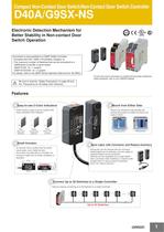
Compact Non-Contact Door Switch/Non-Contact Door Switch Controller D40A/G9SX-NS Electronic Detection Mechanism for Better Stability in Non-contact Door Switch Operation Connection is also possible to a G9SP Safety Controller. •Complies with ISO 13849-1(PLd/Safety Category 3). •The maximum number of Switches that can be connected to a G9SPseries Controller is given below. G9SP-N10S: 15 × 1 system G9SP-N10D/20S: 15 × 2 system For details, refer to the G9SP Series Operation Manual (Cat. No.Z922). For the most recent information on models that have been certified for safety standards, refer to your OMRON website. Be sure to read the “Safety Precautions” on page 28 and the “Precautions for All Safety Door Switches”. Features ● Easy-to-see 2-Color Indicators ● Mount from Either Side Switch status is easy to see at a glance with these red/yellow LED indicators. Red: Open door detected. Yellow: Closed door detected. Not lit: Power OFF or failure Swinging doors ● Small Actuator Sliding doors ● Save Labor with Connector and Reduce Inventory An actuator that is smaller than the switch saves space, even inside the door. Even when mounted with an L-bracket, the actuator's height will not hinder installation or operation. Compact Switch Mount from whichever side provides the easiest wiring path to enable mounting to all types of doors. Wiring time can be reduced with the connector. Cable lengths can be selected, and only cables of required lengths can be purchased. Switches can be integrated into a single Switch with a connector when installing in a machine with multiple doors or various types of machines, which can reduce inventory. Actuator ● Connect Up to 30 Switches to a Single Controller Reduce costs by connecting up to 30 Switches to a single Controller. Up to 30 Switches 1
Open the catalog to page 1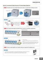
D40A/G9SX-NS Solves Conventional Switch Issues to Provide Stable Detection Issue 1 The Switch does not accurately detect the door when it is closed slowly, resulting in an error. Conventional switch An error can occur if the door is closed slowly with conventional switches. Door closed slowly. Solution 1 Conventional Switches The D40A does not use reed switches and provides stable detection with electronic switches. Slow Slow Magnet Magnet Reed switch contacts Reed switch contacts Error Issue 2 If the switching timing of reed switch contacts 1 and 2 varies too much, the Controller detects an...
Open the catalog to page 2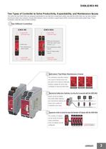
D40A/G9SX-NS Two Types of Controller to Solve Productivity, Expandability, and Maintenance Issues The G9SX-NS and G9SX-NSA are designed specifically for use with Non-contact door switch, and with the G9SX-NSA you can also connect mechanical safety door switches. Among other features, these Controllers support logical AND connections that enable partial stops. These Controllers make the most of D40A Switches. ● Two Different Controllers G9SX-NS G9SX-NSA @Logical AND connection input @Logical AND connection input @D40A input @D40A plus mechanical safety door switch input, channel 1 or 2 @Two instantaneous...
Open the catalog to page 3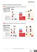
D40A/G9SX-NS Reduce Costs with these New-Concept Controllers Issue 1 Two Controllers are required for emergency stop switches and non-contact door switches. Application ●One hazard. ●The system must be stopped when either a door is opened or an emergency stop switch is pressed. D40B Emergency stop switch * D40A Solution 1 D40B-J1 Emergency stop switch * The D40A Simplifies the Configuration The G9SA must be added to connect the G9SA emergency stop switch. Two Controllers Issue 2 G9SX-NSA With only one G9SX-NSA222-T03@ Controller, both a Non-contact Door Switch and an emergency stop switch can...
Open the catalog to page 4
D40A/G9SX-NS Selection of Safety Controllers for D40A [Connectable Controllers] Safety Controller G9SP Non-contact Door Switch Controller G9SX-NS Safety Controller G9SP Non-contact Door Switch Controller G9SX-NS • Flexible programming by combining function blocks • Extensive system configurations • Decreased work hours by convenient configurator • Easy expansion of output points by an expansion unit • Improved maintainability by LED display • No special programming required Function Blocks Note: For product information, refer to the website at: http://www.ia.omron.com/ Model Number Structure...
Open the catalog to page 5
D40A/G9SX-NS Ordering Information List of Models Non-Contact Door Switches (Switch/Actuator) Classification Appearance Auxiliary outputs Cable length Model 2m D40A-1C2 5m D40A-1C5 Standard models Semiconductor outputs * Connector model 0.15 m D40A-1C015-F * PNP open-collector semiconductor output. Cable with connector Connector Type Cable Length Packing Unit 2m XS2F-D521-DG0-A 5m XS2F-D521-GG0-A 10 m XS2F-D521-JG0-A 1 15 m XS2F-D521-KG0-A 1 20 m Single-end Model XS2F-D521-LG0-A Connector Type Cable Length Model Packing Unit 5 2m XS2W-D521-DG1-A 5 5 5m XS2W-D521-GG1-A 5 10 m XS2W-D521-JG1-A 1...
Open the catalog to page 6
D40A/G9SX-NS Accessories Terminal Block Appearance * Specifications Applicable units Model Remarks Terminal Block with screw terminals (3-pin) G9SX-NSA Y9S-03T1B-02A Two Terminal Blocks (black) with screw terminals, and a set of six code marks to prevent erroneous insertion. Terminal Block with screw terminals (4-pin) G9SX-NS G9SX-EX-@ Y9S-04T1B-02A Two Terminal Blocks (black) with screw terminals, and a set of six code marks to prevent erroneous insertion. Terminal Block with springG9SX-NSA cage terminals (3-pin) Y9S-03C1B-02A Two Terminal Blocks (black) with spring-cage terminals, and a set...
Open the catalog to page 7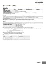
D40A/G9SX-NS Non-contact Door Switches Ratings Power input Item Model G9SX-NS202-@ G9SX-NSA222-T03-@ Rated supply voltage Operating voltage range −15% to 10% of rated supply voltage Rated power consumption * 3 W max. G9SX-EX-@ 24 V DC 4 W max. 2 W max. * Power consumption of loads not included. Inputs Item Model Safety input *1 G9SX-NS202-@/G9SX-NSA222-T03-@ Operating voltage: 20.4 VDC to 26.4 VDC, internal impedance: approx. 2.8 kΩ *2 Feedback/reset input *1. Only applies to the G9SX-NSA222-T03-@. Refers to input other than that from the Non-contact Door Switch. *2. Provide a current equal to...
Open the catalog to page 8All OMRON catalogs and technical brochures
Archived catalogs
 D4F
D4F8 Pages
 D4GS-N
11 Pages
 E4E2
E4E25 Pages
 Fiber SensorBest Selection Catalog
104 Pages
 Fiber Unit E32-LT/LD
4 Pages
 G9SE Series
20 Pages
 R87F / R87T AC Axial Fans
28 Pages
 Displacement Sensors
4 Pages
 Photomicro Sensors
7 Pages
 Switching Power Supplies
16 Pages
 DeviceNet Safety System
30 Pages
 Programmable Terminals NS Series
57 Pages
 Data Logger ZR-RX Series
12 Pages
 Switch Mode Power Supply S8VK-G
22 Pages
 E3FA PHOTOELECTRIC SENSORS
24 Pages
 Safety Controller G9SP
28 Pages
 Round Water-resistant Connectors
31 Pages
 NT series
18 Pages
 Air Particle Sensor ZN-PD-S
2 Pages
 Portable Multi-logger ZR-RX70
12 Pages
 Fiber Sensor Best Selection Catalog
100 Pages
 Code Reader/OCR
24 Pages
 F3SJ Series Safety Light Curtain
108 Pages
 CompoNet
28 Pages
 Vision System FH series
54 Pages
 E9NC-T
2 Pages
 ZW Series
24 Pages
 ZS Series
32 Pages
 ZG2
ZG216 Pages
 FZ4 Series
42 Pages
 VC-DL100
6 Pages
 MS4800
40 Pages
 CP1E
CP1E12 Pages
 CP1
CP112 Pages
 E5AC-T
8 Pages
 H8PS Cam Positioner
32 Pages
 OS32C Safety Laser Scanner
24 Pages
 FQ Vision Sensor
17 Pages
 ZN-PD Air Particle Sensor
16 Pages
 S8EX Switch Mode Power Supply
24 Pages
 CP1L CP series CP1L CPU Unit
36 Pages
 E2EF
E2EF8 Pages
 FQ2 Smart camera
24 Pages
 VT-X700
6 Pages
 Sysmac Catalog
410 Pages
 G5 Series
59 Pages
 E3T Series
6 Pages
 E3T Data Sheet
26 Pages
 E3ZM-C
14 Pages
 E3S-CL
9 Pages
 E3S-A
E3S-A21 Pages
 E3S-R
E3S-R11 Pages
 E3S-GS3E4
3 Pages
 D5A
D5A8 Pages
 D5F
D5F5 Pages
 SC
SC5 Pages
 VB
VB5 Pages
 NL
NL8 Pages
 E6A2-C
5 Pages
 E6B2-C
5 Pages
 E6D-C
E6D-C5 Pages
 E6F-C
E6F-C5 Pages
 E6H-C
E6H-C5 Pages
 E4C-UDA
5 Pages
 E4A-3K
9 Pages
 E4B
E4B12 Pages
 G7J
G7J10 Pages
 G7Z
G7Z9 Pages
 G4Q
G4Q6 Pages
 MMK
MMK14 Pages
 MM
MM17 Pages
 MK-S(X)
12 Pages
 MK-S
MK-S9 Pages
 G2AK
G2AK7 Pages
 G2A-434
7 Pages
 G2A
G2A9 Pages
 G7T
G7T7 Pages
![G2R-[]-S](https://img.directindustry.com/pdf/repository_di/15954/g2r-s-616653_1mg.jpg) G2R-[]-S
G2R-[]-S11 Pages
 LY
LY14 Pages
 NE0A-SCPU01
6 Pages
![NE1A-SCPU0[]-EIP](https://img.directindustry.com/pdf/repository_di/15954/ne1a-scpu0-eip-616667_1mg.jpg) NE1A-SCPU0[]-EIP
NE1A-SCPU0[]-EIP8 Pages
 NE1A-SCPU Series
8 Pages
 61F-GPN-BT / -BC
5 Pages
 E3NC-L/-S
16 Pages
 MY
MY35 Pages
 V680S Series
68 Pages
 V680 series
68 Pages
 TL-L
TL-L5 Pages
 GLS
GLS3 Pages
 F92A
F92A4 Pages
 XS2
XS229 Pages
 XS5
XS525 Pages
 APR-S
APR-S6 Pages
 SAO
SAO13 Pages
 SE
SE15 Pages
 K2CM
K2CM16 Pages
 K8AK-TH
12 Pages
 K8AK-LS
12 Pages
 K8AK-TS/PT
12 Pages
 K8DS-PZ
12 Pages
 K8DS-PU
12 Pages
 K8AK-PW
12 Pages
 K8DS-PA
12 Pages
 K8AK-PA
12 Pages
 K8DS-PM
12 Pages
 K8AK-PM
16 Pages
 K8DS-PH
12 Pages
 K8AK-PH
12 Pages
 K8AK-VW
12 Pages
 K8AK-VS
12 Pages
 K8AK-AW
16 Pages
 K8AK-AS
12 Pages
 G9SA-300-SC
9 Pages
 WS02-CFSC1-E
3 Pages
 DST1 Series
5 Pages
 G9SA
G9SA16 Pages
 G9SB
G9SB10 Pages
 G9SX-LM
28 Pages
 G9SX/G9SX-GS
49 Pages
 G9SX-SM/LM
9 Pages
 G9SX-SM
24 Pages
 G9SP
G9SP28 Pages
 NX-SL/SI/SO
20 Pages
 REGULATION SOLUTIONS
24 Pages
 Sensor Accessories
38 Pages
 SMART REMOTE I/O
12 Pages
 SAFETY APPLICATION HANDBOOK
55 Pages
 Vision Systems
20 Pages


