FORM HOLDING CLAMPS
1 /18Pages

FORM HOLDING CLAMPS
1 /18Pages
Catalog excerpts
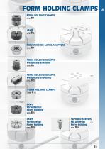
FORM HOLDING CLAMPS FORM HOLDING CLAMPS pag. FORM HOLDING CLAMPS Wedge Style/Round pag. FORM HOLDING CLAMPS Wedge Style/Square pag. FORM HOLDING CLAMPS pag. JAWS for external Form Holding pag. JAWS for internal Form Holding TAPERED SCREWS for internal Form Holding
Open the catalog to page 1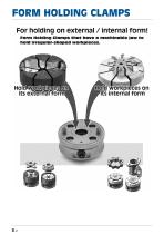
Form Holding Clamps that have a machinable jaw to hold irregular-shaped workpieces
Open the catalog to page 2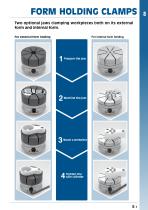
FORM HOLDING CLAMPS Two optional jaws clamping workpieces both on its external form and internal form. For internal form holding For external form holding
Open the catalog to page 3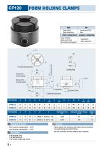
FORM HOLDING CLAMPS Body Part Number Part Number Technical Data: Notes: • Part locating repeatability: ±0.03 • Jaw locating repeatability: ±0.02 • Never tighten the locking screw without: a part mounted, to avoid damag e and deform a tion. • Do not machine the jaw deeper than allowed. • 1 of locking ring . 1 of diamond pin . 1 of socket-hea d cap screw
Open the catalog to page 4
FORM HOLDING CLAMPS Hole Preparation When the locking screw is tightened, the central bottom part of the jaw is pulled down. At the same time the 4 jaw sections tilt toward the center to clamp the circumference of a part. The diaphram clamping mechanism allows securely clamping a part with 4 jaw sections. Different irregularly-shaped parts can be clamped. 0.15mm clamping stroke of each jaw section is perfect for clamping of lost-wax parts, die-cast parts, extruded parts, solid-drawn parts, prefinished parts, etc. How To Use Body Mounting Socket-Head Cap Screws Locking Ring Note : Locate the locking...
Open the catalog to page 5
Locking Ring Part Number Form holding clamps Body Just changing jaws allows holding different parts. 51992212 51992213 How To Remove Jaw When it is hard to remove the jaw by hand, screw a bolt into the jaw-removing tapped hole to push it against the body, for easier removal.
Open the catalog to page 6
Mounting-on-lathe adapters Body Steel (SCM415) Black oxide finish Carburized-hardened Part Number Form holding clamps Using these adapters allow mounting a Form Holding Clamp on the lathe. Mounting-On-Lathe Adapter Form Holding Clamp, Note : A diamond pin included with a FormHolding Clamp is not required in this combination use.
Open the catalog to page 7
FORM HOLDING CLAMPS Wedge Style/Round Steel(S45C) Black oxide finished Steel(S45C) Black oxide finished Part Number Steel(S45C) Black oxide finished Quenched & tempered Steel(S45C) Black oxide finished Quenched & tempered Part Number Technical Information: 1 of locking button 8 27 Spring pin (ø 5x10L for 51992218) (ø Information: Technical6x14L for 51992219) M 10x1.5 -35L Locating repeatability: Furnished Parts: 1 of locking button Spring pin (ø 5x10L for 51992218) (ø 6x14L for 51992219) Clamping Do not tighten the clamping screw without the workpiece Force Allowable Screw Torque Weight Do machinable...
Open the catalog to page 8
FORM HOLDING CLAMPSWedge Style/Round Features: - When the clamp screw is tightened, both jaws tilt toward the center to clamp the circumference of the workpiece. - The clamping stroke is 0.5mm. - Cutting the machinable jaw to the contours of parts allows holding parts of different shapes. - Simple and compact design permits multiple-parts holding arrangement. Part Number How To Machine Jaws ® Setting the locking button Insert the locking button into the jaw, and then tighten the clamp screw to fasten the locking button. (Using a cap screw facilitates setting) (2) Machining the jaw Cut the jaw...
Open the catalog to page 9
FORM HOLDING CLAMPSWedge Style/Square Body Part Number Part Number Furnished Parts: • Do not tighten the clamping screw without the workpiece set to prevent damage and deformation. • Do not machine the Jaws beyond the machinable depth. • 1 of locking button for 51992220/51992222 2 of locking button for 51992221/51992223 • 2 of parallel pin (m6 tollerance) (0 5x10L for 51992220/51992222) (0 6x15L for 51992221/51992223)
Open the catalog to page 10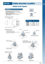
FORM HOLDING CLAMPS Wedge Style/Square Features: • When the clamp screw Is tightened, both Jaws tilt toward the center to clamp the circumference of the workpiece • The clamping stroke is 0.5mm. • Cutting the machinable jaw to the contours of parts allows holding parts of different shapes. • Simple and compact design permits multiple-parts holding arrangement. Clamp Screw Part Number How To Machine Jaws ® Setting the locking button Insert the locking button into the jaw, and then tighten the clamp screw to fasten the locking button. (Using a cap screw facilitates setting)
Open the catalog to page 11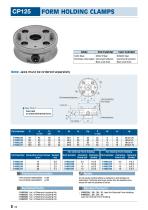
FORM HOLDING CLAMPS Note: Jaws must be ordered separately Body Part Number Part Number Proper Jaws • Part locating repeatability: ±0.03 Do not actuate clamping without a workpiece to avoid damage and • Jaw locating repeatability: ±0.02 deformation. Tightening with torque greater than the allowable screw torque will lower the durability of the jaw. • 51992224: 1 pc. of Diamond Locating Pin • 51992225: 1 pc. of Diamond Locating Pin • 51992226: 1 pc. of Diamond Locating Pin • 51992227: 1 pc. of Diamond Locating Pin • 51992228/...29/...30/...31: Jaws for External Form Holding • 51992232/...33/...34/...35: Jaws...
Open the catalog to page 12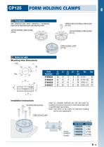
FORM HOLDING CLAMPSFeatures: How to use: Part Number Insert an included diamond pin into the body for locating and secure the body to the fixture plate with 4 socket-head cap screws. Note: Use either of the holes for diamond locating pin for your application.
Open the catalog to page 13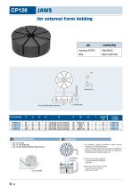
Part Number Furnished Parts: Features • 1 pc. of O-ring • 1 pc. of Locking Ring • 1 pc. of Hex Socket Button Head Screw • The diaphram clamping mechanism allows securely clamping a part with 8 jaw sections. • 0.15mm clamping stroke of each jaw section is perfect for clamping of lost-wax parts, die-cast parts, extruded parts, solid-drawn parts, prefinished parts, etc. ©When the cam cylinder is tightened, the central bottom part of the jaw is pulled down. (D At the same time the 8 jaw sections tilt toward the center to clamp the external form of a part.
Open the catalog to page 14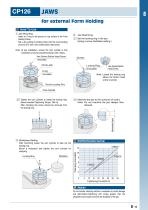
for external Form Holding How To Use Jaw Mounting Insert an O-ring to the groove on top surface of the Form Holding Clamp. Set a Jaw putting its locating holes onto the round locating pins and fix it with a hex socket button head screw. Jaw Machining Set the locking ring in the jaw. (Using a screw facilitates setting.) Note: At jaw installation, ensure the cam cylinder is fully loosened by turning counterclockwise until it stops. Hex Socket Button Head Screw (included) Locking Ring (included) O-ring (included) Hex Socket Button Head Screw Note: Locate the locking ring above the button head screw's...
Open the catalog to page 15All OML catalogs and technical brochures
 CIVI SINTERGRIP
16 Pages
 VCA 5-Axis Machine Tools
14 Pages
 IMG
IMG44 Pages
 MODULAR CLAMPING SYSTEMS
20 Pages
 “GENIUS” & SinterGrip
12 Pages
 Twin Vices
32 Pages
 FAST CLAMPS
108 Pages
 EQUIPMENT CATALOGUE
18 Pages
 STATIC CHUCKS
16 Pages
 VP-N
VP-N12 Pages
 GENIUS
12 Pages
 S P E C I A L O F F E R S 2018
20 Pages
 SinterGrip
20 Pages
 Zero Point Systems
3 Pages
 PRODUCTS OFFERS 2013
8 Pages
 Special jaws and accessories
6 Pages
 FAST-CLAMPS
109 Pages
 TOUCHDEX
20 Pages
 Modular clamping equipment "LC"
10 Pages
 Tombstones, crankwebs, subplates
36 Pages
 GENIU5
12 Pages
 OML Products Offers 2012
6 Pages


Archived catalogs
 OML new products 2008
16 Pages
 OML Products Offers 2010
12 Pages
 Clamping equipment MC
1 Page
 Special offers 2008
2 Pages


- SARRALLE chuck
- SARRALLE vise
- SARRALLE machine vise
- Grade
- SARRALLE machine tool vise
- Workpiece clamping chuck
- SARRALLE precision vise
- SARRALLE manual vise
- Carbide grade
- SARRALLE machining vise
- SARRALLE compact vise
- Rotary indexing table
- SARRALLE power chuck
- 3-jaw workpiece clamping chuck
- Base plate
- Self-centering vise
- SARRALLE screw vise
- SARRALLE 3-jaw turning chuck
- SARRALLE clamping plate