FAST CLAMPS
1 /108Pages

FAST CLAMPS
1 /108Pages
Catalog excerpts

Remote control units pag.
Open the catalog to page 1
Fast Clamps Fast Clamps serve for varied applications in machining and assembly jobs in different industries.
Open the catalog to page 2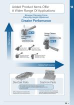
Clamping Force Added Product Items Offer A Wider Range Of Applications Stronger Clamping Force Clamping-Height Adjustment Greater Performance Pull Clamps Heavy Clamping Range:up to 2.5mm Clamping Force:up to 8,000N Swing Clamps Heavy Clamping Range:up to 1.6mm V ^ ■ Clamping Range :2mm Clamping R Clamping Force:up to4.000N Clamping F Clamps, Standard Clamping Range:up to 2.5mm Clamping Force:up to 4,000N Aj Pull Clamps, Standard Swing C f Clamping Range:up to 2mm Clamping Ra Clamping Force :up to 2,500N S Clamping Ft Clamps, Standard Clamping Range :up to 1,8mm Clamping Force :up...
Open the catalog to page 3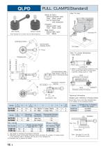
QLPD PULL CLAMPS (Standard) [Body & Cam] Material: SCM440 steel Finish : Black oxide Heat Treat: Quenched and tempered [Handle] Material: S45C steel Finish : Black oxide [Ball Knob] Material: ABS resin Color : Black How To Locate Workpiece 1. Basic Method .Locating Pin 2. Method for clamping and locating a workpiece at a time Give an accuracy shown below to the hole spacing to generate a locating accuracy of ±0.08. (Clamping-Pin Hole Spacing) Clamping-Pin Hole (F7)
Open the catalog to page 4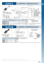
Custom Clamping Pinsldifferent B dimensions) are available on request. *) For ordering, specify workpiece thickness. QLPD-M CLAMPING SCREWS (Standard) Material Finish Heat Treat (Spacing between Clamping-Pin and Clamping-Screw holes) Part Number Custom Clamping Screws (different screw thread sizes) are available on request.
Open the catalog to page 5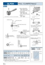
QLPDH PULL CLAMPS (Heavy) QLPDH PULL CLAMPS (Heavy) [Body & Clamp Ring] MateriaI:SCM440 steel Finish :Black oxide Heat Treat :Quenched and tempered [Handle Shank] Material:S45C steel Finish :Black oxide Heat Treat :Quenched and tempered [Handle] MateriaI:Plastic Color :BIack Technical Information Allowable Loads in Machining of Workpiece Bottom Operating Load(N)
Open the catalog to page 6
Part Number *)For ordering, specify workpiece thickness. QLPDH-M CLAMPING SCREWS (Heavy) NEW Material Finish Heat Treat SCM435 Black oxide Quenched and tempered Recommended Spacing Tolerance in Use of Clamping Screws (Spacing between Clamping-Pin and Clamping-Screw holes) T~ ® S I Part Number (Locating Pin Custom Clamping Screws (different screw thread sizes) are available on request
Open the catalog to page 7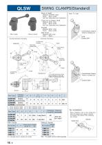
QLSW SWING CLAMPS(Standard) QLSW SWING CLAMPS(Standard) [Body & Shaft] Material: SCM440 steel Finish : Black oxide Heat Treat Quenched and tempered [Clamp Arm & Adaptor Head] Material: S45C steel Finish : Black oxide Heat Treat Quenched and tempered [Handle] Material: S45C steel Finish : Black oxide [Ball Knob] Material: ABS resin Color : Black Note : The handle must be ordered separately. *) Actual clamping height : 31.4 to 32.6 (clamping range :1.2) ##) Actual clamping height : 44 1 to 46.9 (clamping range :1.8) With Handle Without Handle Part Number ***) Allowable load to operate the handle...
Open the catalog to page 8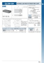
MACHINABLE CLAMP ARMS FOR STANDARD SWING CLAMPS Technical Infomation Allowable Loads in Machining of Workpiece Bottom Workpiece Fixture Plate tt) Actual clamping height:33.4 to 34.6 (clamping rangeH.2) *M) Actual clamping heights 1 to 47.9 (clamping range: 1.8)
Open the catalog to page 9
QLSWH SWING CLAMPS (Heavy) [Body/Cam/Handle] Material: SCM440 steel Finish : Black oxide Heat Treat: Quenched and tempered [Bolt] Material: SCM435 steel Finish : Black oxide Heat Treat: Quenched and tempered [Clamp Arm/Holder/Handle Shank] Material: S45C steel Finish : Black oxide Heat Treat: Quenched and tempered [Adjustment Knob] Material: S45C steel Finish : Black oxide [Handle] Material: Plastic Color : Black Part Number Part Number *) Allowable load to operate the handle
Open the catalog to page 10
Recommeded Dimensions *) See page 138 clamping force vs. clamp-arm length Clamp Arm Installation/Removal Instructions To install a clamp arm, 1. Fit it onto the shaft getting the stop pin received in the stop-pin slot provided on the clamp-arm bottom. 2. Place the adaptor head onto the shaft getting the shaft fitted into the shaft-receiving pocket in the adaptor head, and then lock the adaptor head using a hex. socket head cap screw. 3.Tighten the ball plungers inside the clamp arm. To remove the clamp arm, follow the above steps back. How To Determine D Dimensions Series Clamp Arm Customization...
Open the catalog to page 12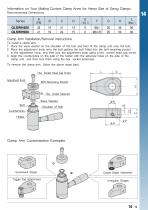
Recommended Dimensions 1. Place the wave washer on the shoulder of the bolt and then fit the clamp arm onto the bolt. 2. Place the adjustment knob onto the bolt getting the bolt fitted into the bolt-receiving pocket in the adjustment knob, and then lock the adjustment knob using a hex. socket head cap screw. 3. Align the countersinks on the side of the holder with the setscrew holes on the side of the clamp arm, and then lock them using the hex. socket setscrews. To remove the clamp arm, follow the above steps back. Clamp Arm Customization Examples 14.13
Open the catalog to page 13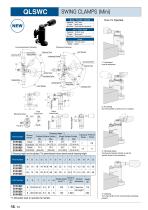
SWING CLAMPS (Mini) Body / Handle / Spindle Part Number *) Clamping height can be adjusted. The parenthesised values denote actual clamping height. Part Number **) Allowable load to operate the handle
Open the catalog to page 14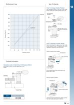
How To Operate How To Change Handle Position The dodecagonal socket in the hub of the handle allows changing the handle operating angle by 30°. How To Release Locked Handle When turned beyond the clamping end, the handle will be locked with a click. The locked handle can be released by following the instructions below. Technical Information Allowable Loads in Machining of Workpiece Bottom Ensure that any force more than stated below is not applied. Turn the handle beyond the locked position until another click is made. When the spindle is installed, Lower the arm at the handle locked position...
Open the catalog to page 15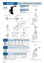
SWING CLAMPS (Mini) WITH CAM HANDLE Body / Washer / Spindle Part Number *) Clamping height can be adjusted. The parenthesised values denote actual clamping height. Part Number Part Number **) Allowable load to operate the handle 14.16 How To Operate
Open the catalog to page 16
Performance Curve Technical Information
Open the catalog to page 17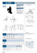
SWING CLAMPS (Mini) FOR TORQUE CONTROL Body / Washer / Flange Nut / Spindle • Designed for clamping-force control with a torque wrench • Screw clamping mechanism allows for longer clamping stroke and greater clamping force. Rough Surface Contact Turning the flange nut allows the arm to swing into position for clamping.
Open the catalog to page 18All OML catalogs and technical brochures
 CIVI SINTERGRIP
16 Pages
 VCA 5-Axis Machine Tools
14 Pages
 IMG
IMG44 Pages
 MODULAR CLAMPING SYSTEMS
20 Pages
 “GENIUS” & SinterGrip
12 Pages
 Twin Vices
32 Pages
 EQUIPMENT CATALOGUE
18 Pages
 STATIC CHUCKS
16 Pages
 VP-N
VP-N12 Pages
 FORM HOLDING CLAMPS
18 Pages
 GENIUS
12 Pages
 S P E C I A L O F F E R S 2018
20 Pages
 SinterGrip
20 Pages
 Zero Point Systems
3 Pages
 PRODUCTS OFFERS 2013
8 Pages
 Special jaws and accessories
6 Pages
 FAST-CLAMPS
109 Pages
 TOUCHDEX
20 Pages
 Modular clamping equipment "LC"
10 Pages
 Tombstones, crankwebs, subplates
36 Pages
 GENIU5
12 Pages
 OML Products Offers 2012
6 Pages


Archived catalogs
 OML new products 2008
16 Pages
 OML Products Offers 2010
12 Pages
 Clamping equipment MC
1 Page
 Special offers 2008
2 Pages


- SARRALLE chuck
- SARRALLE vise
- SARRALLE machine vise
- Grade
- SARRALLE machine tool vise
- Workpiece clamping chuck
- SARRALLE precision vise
- SARRALLE manual vise
- Carbide grade
- SARRALLE machining vise
- Rotary indexing table
- SARRALLE compact vise
- SARRALLE power chuck
- 3-jaw workpiece clamping chuck
- Base plate
- Self-centering vise
- SARRALLE screw vise
- SARRALLE 3-jaw turning chuck
- SARRALLE clamping plate