 Website:
OMICRON electronics
Catalog excerpts

UHF 800 Ultra-high frequency (UHF) partial discharge measurement and analysis system
Open the catalog to page 1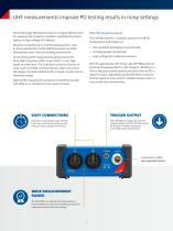
UHF measurements improve PD testing results in noisy settings UHF PD measurements Partial discharge (PD) measurement is a highly-effective tool for assessing the insulation condition and detecting critical defects in high-voltage (HV) devices. The UHF 800 system is a modular solution for UHF PD measurement and analysis on: However, conventional on-site PD measurements, such as those specified by the IEC 60270 standard, are often affected by noise in the surrounding environment. >> Gas-Insulated Switchgear/Lines (GIS/GIL) >> Oil-filled power transformers >> High-voltage (HV) cable...
Open the catalog to page 2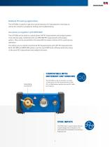
Multiple PD testing applications The UHF 800 is suited for type and routine testing in HV laboratories or test bays as well as for onsite HV acceptance testing and troubleshooting. Use alone or together with MPD 800 The UHF 800 can be used as a stand-alone UHF PD measurement and analysis system. It can also be easily combined with our MPD 800 PD measurement and analysis system. They can be connected to the same MCU2 master control unit for synchronous operation. This allows you to extend conventional PD measurements with UHF PD measurements. Both UHF 800 and MPD 800 systems use the same MPD...
Open the catalog to page 3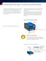
Complete system for single- or multi-channel UHF PD testing A single-channel UHF 800 system consists of one UHF 800 data acquisition unit, a rechargeable RBP1 battery, an MCU2 master control unit as well as MPD Suite software. The MCU2 converts the fiber-optic connection from the data acquisition unit to a USB connection for your notebook or office computer. You can easily connect up to 12 UHF 800 data acquisition units via daisy chain with fiber optic cables to the MCU2 master control unit. The MPD Suite software provides you with an overview of connected devices and enables you to set up...
Open the catalog to page 4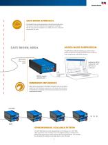
SAFE WORK APPROACH You benefit from a clear separation of the HV and safe working areas as only the measurement equipment is placed in the HV area. The test engineer can safely work on a computer outside the HV area. SAFE WORK AREA ADDED NOISE SUPPRESSION The MPD Suite software provides you with various additional gating and sophisticated tools for effective noise suppression and reliable analysis. OMICRON fiber-optic cable Laptop or office computer with MPD Suite software MCU2 master control unit MINIMIZED INFLUENCES Fiber optic connections to the MCU2 master control unit and to additional...
Open the catalog to page 5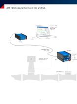
Laptop or office computer with MPD Suite software OMICRON fiberoptic cable Optional: Sync via voltage from VT
Open the catalog to page 6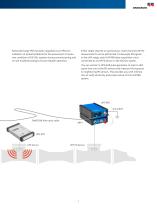
Partial discharge (PD) has been regarded as an effective indication of potential defects for the assessment of insulation condition of GIS/GIL systems during commissioning and on-site troubleshooting to ensure reliable operation. Either single-channel or synchronous, multi-channel UHF PD measurements can be performed. To decouple PD signals in the UHF range, each UHF 800 data acquisition unit is connected to a UHF PD sensor in the GIS/GIL system. You can connect a UPG 620 pulse generator to inject a UHF signal into one of the PD sensors and measure the response in neighboring PD sensors....
Open the catalog to page 7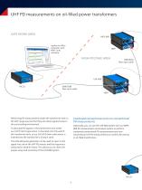
UHF PD measurements on oil-filled power transformers SAFE WORK AREA Laptop or office computer with MPD Suite software HIGH-VOLTAGE AREA OMICRON fiber-optic cable OMICRON fiber-optic cable RBP1 Combined conventional and non-conventional PD measurements Performing PD measurements inside the transformer tank in the UHF range ensures that they are robust against noise in the surrounding environment. Optionally, you can use the UHF 800 system with our MPD 800 PD measurement and analysis system to perform combined conventional PD measurements and nonconventional UHF PD measurements to confirm PD...
Open the catalog to page 8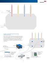
Triggers acoustic PD signals for precise defect localization You can also connect our PDL 650 acoustic PD measurement system to the trigger output of the UHF 800 data acquisition unit. The UHF 800 system can then be set up to trigger the PDL 650 system to triangulate the acoustic signals from multiple sensors to pinpoint the actual PD source inside the transformer. OMICRON fiber-optic cable Acoustic sensor Laptop or office computer with PDL 650 software Laptop or office computer with MPD Suite software
Open the catalog to page 9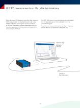
UHF PD measurements on HV cable terminations Partial discharge (PD) diagnosis using Ultra-High Frequency (UHF) measurements has also been proven to be a very reliable method for assessing the insulation condition of HV cable terminations, because measurements in this frequency range are not influenced by noise typical in the surrounding environment. Our UCS1 UHF sensor is mounted between the cable sheath and the ground structure of the cable termination to decouple PD signals. To synchronize measurements to the test or grid frequency, the UHF 800 can use signal from a Rogowski coil. Laptop...
Open the catalog to page 10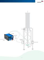
Connection Terminal Ground switch Rogowski Coil
Open the catalog to page 11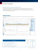
Software highlights Selectable measurement modes for enhanced sensitivity The MPD Suite software supports the UHF 800 with different measurement modes which allow you to achieve a high signal-to-noise ratio and perform sensitive measurements on GIS/GIL, oil-filled power transformers and HV cable terminations. The Wideband Mode is a standard feature. The Spectrum View and Medium Band Mode are features of the UHF Multiband Software Module (see page 23). WIDEBAND MODE The UHF 800 can evaluate the signal spectrum from 100 MHz to 2 GHz with a sensitive setting covering the whole measurement...
Open the catalog to page 12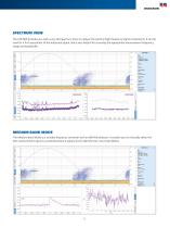
SPECTRUM VIEW The UHF 800 provides you with a very fast Spectrum View to analyze the existng high-frequency signal components. It can be i used for a first assessment of the measured signal, and is very helpful for choosing the appropriate measurement frequency range and bandwidth. MEDIUM BAND MODE The Medium Band Mode is a tunable frequency converter with an 80 MHz detector. It enables you to manually select the best measurement signal to avoid disturbance signals and to identify even very small defects.
Open the catalog to page 13All OMICRON electronics catalogs and technical brochures
-
Primary Test ManagerTM
16 Pages
-
MCT 085
2 Pages
-
PDL 650
8 Pages
-
CPC 100
44 Pages
-
OMICRON Products and Solutions
25 Pages
-
InSight
4 Pages
-
MONTESTO 200
16 Pages
-
ISIO 200
8 Pages
-
CMControl R
12 Pages
-
CMControl P
8 Pages
-
CMS 356
2 Pages
-
IEDScout
8 Pages
-
Bode 100 - Technical Data
4 Pages
-
CMA 156
1 Pages


