- Catalogs
- OMICRON electronics
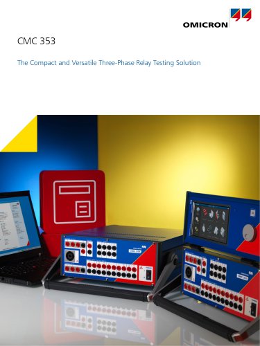
- CMS 356
- Company
- Products
- Catalogs
- News & Trends
- Exhibitions
CMS 356
1 /2Pages

CMS 356
1 /2Pages
Catalog excerpts

CMS 356 CMS 356: 6 Phase Current + 4 Phase Voltage Amplifier The CMS 356 is a voltage and current amplifier for analog low-level signals provided by a CMC test set or by any other signal source, such as a digital real-time power system simulator. When used in combination with a CMC test set, the amplifier extends the capabilities of the test set to provide additional output channels and higher amplitudes. The high-amplitude and high-power current outputs make it equally suitable for testing modern numerical relays as well as high-burden electromechanical relays. The outputs of the voltage amplifier and the current amplifier are galvanically separated from each other and also from mains. Configuration and monitoring of the device status of the CMS 356 amplifier can be performed via the easy-to-use web interface. Key features: >> Six analog low-level inputs with selectable range (±7.071 Vpk or ±10 Vpk) >> Numerous output configurations, for example, 3 x 300 V + 3 x 64 A or 6 x 32 A >> Calculation and output of residual voltage and current >> Parallel connection of several CMS 356 units for even higher current amplitudes >> All current and voltage outputs are fully overload and short circuit proof >> Protection against voltage transient signal and over temperature Technical Data1 Current generators Setting range 6-phase AC (L-N) Voltage generators Setting range 4-phase AC (L-N) 1 x 0 ... ±180 A (Group A II B) 6 x 430 VA typ. at 25 A 6 x 250 W guar. at 20 A 3 x 860 VA typ. at 50 A 3 x 500 W guar. at 40 A 1 x 1000 VA typ. at 80 A 1 x 700 W guar. at 80 A 1 x 1740 VA typ. at 50 A 1 x 1100 W guar. at 40 A 1 x 1740 VA typ. at 25 A 1 x 1100 W guar. at 20 A 1 x 1400 W typ. at ±80 A 1 x 1000 W guar. at ±80 A Accuracy 3 Distortion (THD+N) 5 Max. compliance voltage (L-N)/(L-L)/(L-L-L-L) Connection banana sockets Connection combination socket Distortion (THD+N) 5 Ranges Connection All data specified are guaranteed, except where indicated otherwise. OMICRON guarantees the specified data for one year after factory calibration, within 23 °C ±5 °C (73 °F ±10 °F) in the frequency range from 10 to 100 Hz and after a warm-up phase > 25 minutes 2 Typical AC values valid for inductive loads (e.g. e/m relays) 3 Rload: 0 ... 0.5 Ω 4 rd. = reading, rg. = range 5 THD
Open the catalog to page 1
Miscellaneous Weight Dimensions (W x H x D, without handle) PC connection Signal indication (LED) Status LEDs Connection to ground (earth) Hardware diagnostics Galvanically separated groups 16.3 kg (35.9 lb) 450 x 145 x 390 mm (17.7 x 5.7 x 15.4 in) Two Ethernet ports: 10/100/1000 Base-TX > 42 V for voltage and current outputs For each amplifier output to indicate hardware status (e.g. overload condition) 4 mm (0.16 in) banana socket (rear side) Self diagnostics upon each start-up The following groups are galvanically separated from each other: mains, voltage amplifier output, current amplifier...
Open the catalog to page 2All OMICRON electronics catalogs and technical brochures
 Primary Test ManagerTM
16 Pages
 MCT 085
2 Pages
 PDL 650
8 Pages
 CPC 100
44 Pages
 OMICRON Products and Solutions
25 Pages
 InSight
4 Pages
 MONTESTO 200
16 Pages
 ISIO 200
8 Pages
 CMControl R
12 Pages
 CMControl P
8 Pages
 IEDScout
8 Pages
 Bode 100 - Technical Data
4 Pages
 CMA 156
1 Page


- Transformer
- Measuring device
- Automation software solution
- Management software solution
- Dry transformer
- Analysis software solution
- OMICRON measuring system
- Digital I/O
- Process software
- Automatic analyser
- Windows software
- Calibration system
- IO module
- Benchtop analyser
- Analog I/O
- Portable tester
- Digital IO module
- Capacitor
- Warning light
- Portable analyzer