


Ares angle seat valve with special connections
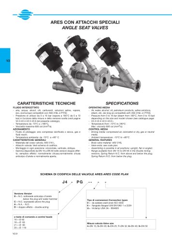
Ares angle seat valve with special connections
Technical Specifications
The ARES angle seat valves are designed for use with various fluids including air, water, alcohol, oils, fuels, saline solutions, and steam, provided compatibility with AISI 316L stainless steel and PTFE is ensured. Operating pressure ranges from 0 to 16 bar, with steam applications at 180°C limited to 10 bar. Temperature range spans from -10°C to +180°C. Maximum fluid viscosity is 600 cst (mm²/s). The driving medium can be compressed air (lubricated or dry), gases, or neutral fluids. Ambient temperature for operation is between -10°C and +60°C. Valve bodies are made of AISI 316L stainless steel. Valves can be mounted in any orientation: horizontal, vertical, or oblique.
Valve Versions and Configurations
- Double Acting (D): Bidirectional operation.
- Spring Return Normally Closed (N.C.): Available with flow either below (anticolpo d’ariete - anti water hammer) or above the plug.
- Spring Return Normally Open (N.O.): Flow from below the plug.
Valve sizes range from DN 15 to DN 50. Connection types include weld ends (ISO 4200), flanged ends (UNI EN 1092-1 and 2229), and tri-clamp (USA 3A - BS4825). Special flange versions such as ANSI 150 RF and reduced flanges are available on request.
Valve Coding Scheme
The valve code consists of several elements:
- Version: 's' = N.C. below plug (anti water hammer), 'c' = N.C. above plug, 'a' = N.O., 'd' = double acting.
- Control head diameter: 16 = 50 mm, 18 = 63 mm, 21 = 90 mm, 23 = 110 mm.
- Connection type: 9 = weld ends, 6 = flanged, u = tri-clamp.
- Valve size: 4 = DN 15, 5 = DN 20, 6 = DN 25, 7 = DN 32, 8 = DN 40, 9 = DN 50.
- Face-to-face dimension: According to DIN 3202 part F1.
Dimensions and Mechanical Details
Detailed dimensional tables provide measurements for control heads, valve bodies, and flange interfaces for all sizes and connection types. Control heads are adjustable 360° for flexible installation. Standard flange dimensions comply with UNI EN 1092-1 and UNI 2229, with ANSI 150 RF and reduced flange options available on request. Weld ends conform to UNI ISO 4200, with optional DIN 11850 and ISO 2037 standards upon request. Tri-clamp connections follow 3A sanitary standards.
Performance Characteristics
Pressure and flow diagrams illustrate the relationship between control pressure and differential pressure (ΔP) across the valve for various control head sizes (50 mm, 63 mm, 90 mm, 110 mm). These diagrams differentiate valve versions by flow direction (above or below the plug) and valve type (N.C., N.O., double acting). Maximum allowable differential pressure varies by valve size and version, with typical maximum ΔP values up to 16 bar.
Flow and Kv Values
Tables list valve bore sizes, Kv values (flow coefficient in m³/h), control head diameters, control pressure ranges, and maximum operating pressures. For example, a 1" valve with a 50 mm control head has a Kv of approximately 10.5 m³/h and operates up to 10 bar control pressure. Clamp connections may reduce the effective bore (e.g., from 15 mm to 9.5 mm) due to clamp size limitations.
Weight and Materials
Valve weights are provided for each size and configuration, all constructed from AISI 316L stainless steel ensuring corrosion resistance and durability in demanding industrial environments.
Recommendations and Best Practices
- Ensure fluid compatibility with AISI 316L and PTFE materials.
- Choose valve version based on flow direction and application needs to avoid water hammer (preferably N.C. with flow below the plug).
- Install valves in any orientation as required by the system design.
- Refer to pressure and flow diagrams to select appropriate control pressure and valve size for desired operating conditions.
- Request special flange or connection types if standard options do not meet installation requirements.
Summary
The ARES angle seat valves offer versatile configurations suitable for a wide range of industrial fluids and operating conditions. Their robust construction, multiple connection options, and detailed performance data enable precise selection and reliable operation in systems requiring pressures up to 16 bar and temperatures up to 180°C. The comprehensive coding system and adjustable control heads facilitate customization and ease of installation.
Catalog excerpts

ARES con attacchi speciali angle seat valveS V2 caratteristiche tecniche SPECIFICATIONS fluido intercettato - aria, acqua, alcool, olii, carburanti, soluzioni saline, vapore, ecc..(comunque compatibili con AISI 316L e PTFE) - Pressione di utilizzo da 0 a 16 bar (vapore a 180°C da 0 a 10 bar) in funzione della misura e della versione scelta (vedi pagine V2.3-V2.4-V2.5-V2.6 del presente catalogo). - Temperatura da -10°C a +180°C. - Viscosità massima 600 cst (mm2/s). azionamento - Fluido di pilotaggio: aria compressa lubrificata o secca, gas e fluidi neutri; - Temperatura ambiente: da -10°C a +60° C caratteristiche generali - Materiale del corpo valvola: AISI 316 L - Attacchi valvola: Vedi schema di codifica. - Montaggio in ogni posizione: orizzontale, verticale, obliqua. - Gamma disponibile da DN 15 a DN 50 nelle versioni doppio effetto; semplice effetto: normalmente chiusa,normalmente chiusa anticolpo d’ariete e normalmente aperta. Operating media - Air, water, alcohol, oil, petroleum products, saline solutions, steam, etc. (as long as compatible with AISI 316L or PTFE). - Pressure from 0 to 16 bar (steam from 180°C, from 0 to 10 bar) depending on the size and model chosen (see catalogue page: - V2.3-V2.4-V2.5-V2.6 ). - Temperature from –10°C to 180°C. Max. viscosity 600 cst (mm2/s). Control media - Driving media: compressed air, lubricated or dry, gas or neutral media. - Ambient temperature: -10°C to +60°C general features - Body valve material: AISI 316L - Valve ends: see code plan. - Assembling is possible in all positions: upright, flat or angled. - Range available from DN 15 to DN 50 in the Double Acting versions, Spring Return N.C. from above and below the plug, Spring Return N.O. from below the plug. Schema di codifica delle valvole ares Ares code plan j4 - pg Versione Version S = N.C. sottosede anticolpo d’ariete below the plug anti water hammer C = N.C. soprasede above the plug A = N.A. - N.O. D = doppio effetto - double acting ø teste di comando ø control heads 16 = ø 50 18 = ø 63 21 = ø 90 23 = ø 110 V2.9 -- - - Tipo di connessioni Connection types 9 = da saldare weld ends ISO 4200 6 = flangiate flanged UNI EN1092-1 e 2229 U = triclamp USA 3A - BS4825 Misura valvola Valve size 4=DN 15; 5=DN 20; 6=DN 25; 7=DN 32; 8=DN 40; 9=DN 50
Open the catalog to page 1
ares Ru o C tare lo ck in w se ise n ro so ta or tio ar n io Attacchi clamp 3a triclamp ends 3a dimensioni dimensions Testa di comando orientabile a 360° Control head adjustable at 360° V2 1/2” - 3/4” 1/8” ISO 228 PN 16 1” - 1”1/2 - 2” * * esecuzioni speciali su richiesta e per quantità * special version on request a richiesta versioni ISO 2852 ISO 2852 version on request Pressione di utilizzo da 0 a 16 bar (vapore a 180°C da 0 a 10 bar) in funzione della misura e della versione scelta (vedi pagine V2.13-V2.14-V2.15-V2.16 del presente catalogo) Pressure from 0 to 16 bar (steam from 180°C, from...
Open the catalog to page 4
clamp 3a Versioni e codifiche Versions and codes N.C. Normalmente chiusa bidirezionale. Con ingresso sotto l’otturatore si evita il colpo d’ariete. N.C. Normally Closed bidirectional. With the flow coming from below the plug you avoid water hammering. Con ingresso sotto l’otturatore With the flow from below the plug codice code aisi 316 Passaggio Kv ø Testa comando Bore mm m3/h ø control head p comando bar p control bar Min Max Peso Weight Kg. AISI 316 p intercettata p operating ∆P max. bar j4spg16u4 1/2” 50 4 10 16 1 j4spg16u5 3/4” 15 5,7 50 4 10 16 1,1 j4spg16u6 1” 20 10,5 50 4 10 10 1,2 j4spg18u6...
Open the catalog to page 5
clamp 3a Versioni e codifiche Versions and codes N.C. Normalmente chiusa con ingresso sopra l’otturatore N.C. Normally Closed with the flow from above the plug codice code aisi 316 CLAMP SIZE j4cpg16u4 1/2” j4cpg16u5 3/4” j4cpg16u6 p comando bar p control bar Min Max Passaggio Kv ø Testa comando Bore mm m3/h ø control head 1” 9,5(*) 3,4 Peso Weight Kg. AISI 316 p intercettata p operating ∆P max. bar 50 50 15 5,7 V2 1,8 10 diagram n° 5 1 1,8 10 diagram n° 5 1,1 20 10,5 50 1,8 10 diagram n° 5 1,2 32 63 1,8 j4Cpg21u8 11/2” 32 29 90 1,8 8 diagram n° 7 3 j4Cpg21u9 2” 40 46 90 1,8 8 diagram n° 7 3,7...
Open the catalog to page 6
clamp 3a Versioni e codifiche Versions and codes N.A. Normalmente aperta con ingresso sotto l’otturatore N.O. Normally Open with flow from below the plug codice code aisi 316 Passaggio Kv ø Testa comando Bore mm m3/h ø control head j4apg16u4 1/2” j4apg16u5 3/4” j4apg16u6 9,5(*) 3,4 1” j4apg18u8 p comando bar p control bar Min Max Peso Weight Kg. AISI 316 p intercettata p operating ∆P max. bar 50 1,8 10 diagram n° 9 1 50 15 5,7 1,8 10 diagram n° 9 1,1 20 10,5 2” 50 1,8 10 diagram n° 9 1,2 32 11/2” j4apg21u9 63 1,8 90 1,8 8 diagram n° 11 3,7 28,5 40 46 10 diagram n° 10 2,6 (*) Il passaggio valvola...
Open the catalog to page 7
clamp 3a Versioni e codifiche Versions and codes Doppio effetto bidirezionale Double Acting bidirectional codice code aisi 316 Passaggio Kv ø Testa comando Bore mm m3/h ø control head CLAMP SIZE j4dpg16u4 1/2” j4dpg16u5 3/4” j4dpg16u6 9,5(*) 3,4 p comando bar p control bar Min Max Peso Weight Kg. AISI 316 p intercettata p operating ∆P max. bar 50 50 15 5,7 V2 0,8 8 diagram n° 13 1 0,8 8 diagram n° 13 1,1 1” 20 10,5 50 0,8 8 diagram n° 13 1,2 j4dpg18u8 11/2” 32 28,5 63 0,8 8 j4dpg18u9 2” 40 35 63 0,8 8 diagram n° 14 2,3 j4spg21u9 2” 40 46 90 0,8 8 diagram n° 15 3,6 diagram n° 14 2 (*) Il passaggio...
Open the catalog to page 8All OMAL Spa catalogs and technical brochures
 MAGNUM & THOR
7 Pages
 General Catalogue
592 Pages
 "EA" ON-OFF rotary type
9 Pages
 Special ends
21 Pages
 Angle seat valves
33 Pages
 ITEM 545
7 Pages
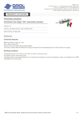 Pneumatic actuators
6 Pages
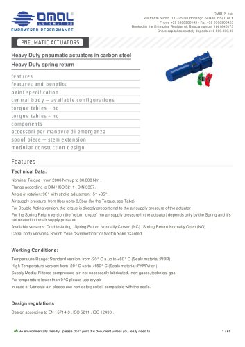 Heavy Duty spring return
65 Pages
 Heavy Duty Double acting
29 Pages
 Pro-Chemie 60
7 Pages
 Trunnion ball valves Supreme
18 Pages
 stainless steelANSI 900-1500
13 Pages
 TFM1600 seats
1 Page
 Stainless steel ball valve
11 Pages
 Hercules
10 Pages
 Vip - Pneumatic axial valve
7 Pages
 CONVERSION DA ? SR
4 Pages
 CONVERSION SR ? DA
4 Pages
 TRANSMISSION MECHANISM
6 Pages
 OMAL ACTUATORS TESTING
4 Pages
 TWO STAGE
2 Pages
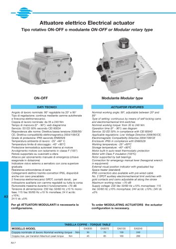 ELECTRICAL ACTUATOR EA
6 Pages
 ELECTRICAL ACTUATOR AE
6 Pages
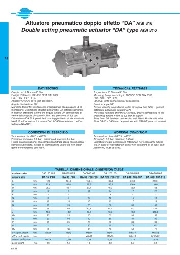 DOUBLE ACTING "DA" AISI 316
2 Pages
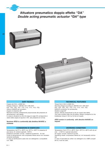 DOUBLE ACTING "DA"
4 Pages
 ART. 460-461
4 Pages
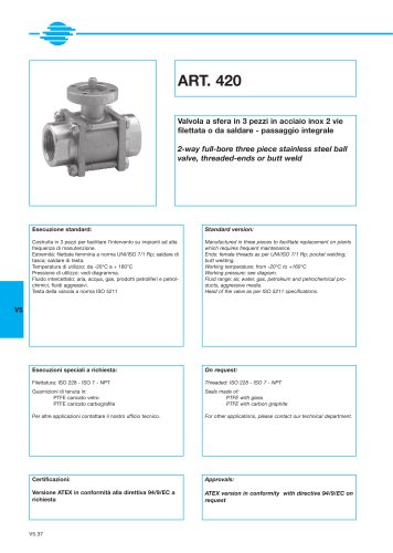 ART. 420
4 Pages
 V415 ART. 415
4 Pages
 ART. 400-401
4 Pages
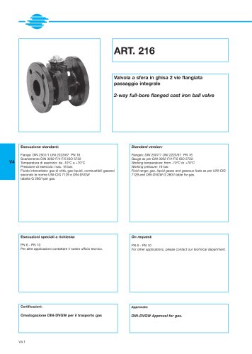 ART. 216
4 Pages
 ART. 160-161
4 Pages
 ART. 153
4 Pages
 ART. 116
4 Pages
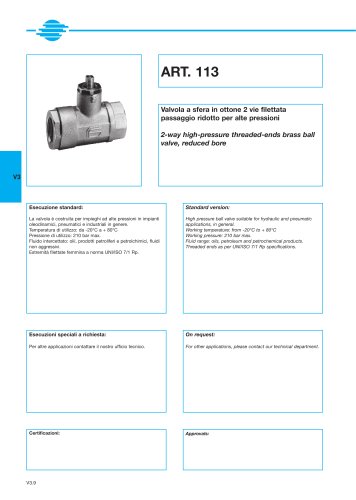 ART. 113
4 Pages
 ART. 101
4 Pages
 ART. 100
4 Pages
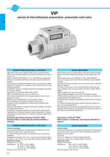 Pneumatic axial valve
8 Pages
 ARES WITH MANUAL DRIVE
2 Pages









Archived catalogs
 CHEMICAL NICKEL
6 Pages
 OMAL - General Catalogue (en,it)
274 Pages