PVWC 011, 014, 022 Pump
1 /16Pages

PVWC 011, 014, 022 Pump
1 /16Pages
Catalog excerpts

PVWC TWO-WAY VARIABLE DELIVERY HYDROSTATIC (CLOSED LOOP) PUMPS
Open the catalog to page 1
Performance Assurance page 3 Single Pump Lever Operated with Neutral Bypass 11 Electrohydraulic Servo Valve 11 Copyright 2007 ■ The Oilgear Company mAU Rights Reserved
Open the catalog to page 2
PERFORMANCE ASSURANCE – Standard With Every Oilgear pump As a customer, you also benefit from access to commitment to stay with your installation until You’ll find factory trained and field-experienced with our Performance Assurance — a corporate Oilgear’s impressive technical support network. our equipment performs as specified. application engineers on staff at every Oilgear Hydraulic equipment and systems have been who can access the records and knowledge learned Oilgear’s primary business since 1921. For decades, we have developed hydraulic techniques to meet the unique needs and unusual...
Open the catalog to page 3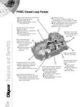
PVWC Closed Loop Pumps Cylinder carried in polymerous journal bearing. n Provides longer bearing life. 2 n Permits compact design. n Allows operation with low viscosity or other special fluids. Hardened cylinder surface running on hardened valve plate. n Greater resistance to contamination. n Provides longer life. n Allows operation with low viscosity or other special fluids. Large selection of controls. n Several types of mechanical, hydraulic and electrohydraulic servo valve controls are available. n Allow cushioned “across-center” delivery reversal. n Field interchangeability without disconnecting...
Open the catalog to page 4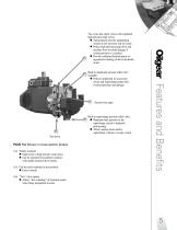
Two cross-line check valves with (optional) high pressure relief valves. n Automatically provide replenishing volume to low pressure side of circuit. n Protect high pressure pump drive and machine from overload damage if system pressure is exceeded. n Provide cushioned hydrodynamic or regenerative braking of driven hydraulic motor. PLUS Not Shown in cross section photos (14) Totally enclosed. n Impervious to high pressure wash down. n Can be operated in hazardous locations, with totally enclosed drive motors. (15) Can be easily mounted in any position. n Easy to install. Built-in supercharge...
Open the catalog to page 5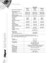
PVWC-011 Maximum Piston Pump Displacement 0.66 cipr 10.8 cc/rev Operating Pressure (see Note 1) Rated Continuous 4000 psi (275 bar) Maximum Intermittent (10% of duty) 4500 psi (310 bar) Peak 5000 psi (350 bar) Output Flow (see Note 2) (@ 1800 rpm & Rated Cont Pressure) 4.1 gpm (15.5 lpm) Input Shaft Speed Minimum 600 rpm Continuous 3600 rpm Intermittent 4000 rpm Charge Pressure (@ 1800 rpm) Nominal 75 psi (5 bar) Minimum 30 psi (2 bar) Case Pressure Maximum Continuous 15 psi (1 bar) Maximum Intermittent 100 psi (7 bar) Hydraulic Fluid Temp (@ pump inlet) Minimum -40° F (-40° C) Maximum 200° F...
Open the catalog to page 6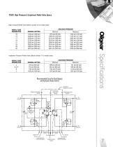
PVWC High Pressure & Implement Relief Valve Specs High Pressure Relief Valve (Block number 16 of model code) Cracking Pressure Model CODE Designation NominaL Setting J E or F K L Cracking Pressure Maximum Recommended Circuit for Dual Outputs and Hydraulic Stroke Control External Line (Supplied by customer) To Hydraulic Stroke Control SAE #8 Charge Pressure Outlet SAE #8 High Pressure Relief Valve Charge Pressure Inlet SAE #8 A2 SAE #8 High Pressure Relief Valve Implement Pressure Relief Valve (Block number 17 of model code) Charge Pressure Relief Valve 75 psi High Pressure Relief Valve High Pressure...
Open the catalog to page 7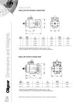
SINGLE PUMP SINGLE UNIT WITH INTEGRAL CHARGE PUMP PUMP MOUNT * WEIGHTS ARE FOR MN/MS CONTROLS. SINGLE UNIT WITHOUT CHARGE PUMP * WEIGHTS ARE FOR MN/MS CONTROLS. ADD 2.4 LBS (1,1 KG) All dimensions are approximate. For detailed information, contact your Oilgear representative.
Open the catalog to page 8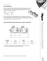
DUAL PUMP PUMP COMBINATIONS Two or more PVWC variable delivery pumps can be integrally coupled together, without the use of an adapter, and driven from a single shaft. NOTE: the total torque of the combination may not exceed that shown in the table below. The torque may be divided between multiple units in any fashion as long as the total does not exceed this value. Unit Size When used individually to operate individual hydraulic motors, the individual pump controls can be used to synchronize speeds or to establish differential speeds. If the main driveshaft speed varies due to load etc., the...
Open the catalog to page 9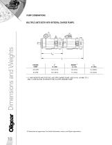
PUMP COMBINATIONS MULTIPLE UNITS BOTH WITH INTEGRAL CHARGE PUMPS. CHARGE PUMP * “L” AND WEIGHTS ARE FOR THE .425 CIPR CHARGE PUMP. ADD 0.4 IN. (10 mm) TO “L” AND 1.4 LBS (0,6 KG) TO WEIGHT FOR .64 CIPR CHARGE PUMP. All dimensions are approximate. For detailed information, contact your Oilgear representative.
Open the catalog to page 10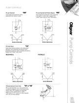
PUMP CONTROLS Lever Operated Varies displacement and direction of flow proportional to the rotation of a pintle. Lever Operated with Neutral Bypass “MS” Varies displacement and direction of flow proportional to the rotation of a pintle which is equipped with “neutral” bypass to prevent “creep” when centered. Single-spring centering mechanism with external neutral adjustment. Varies displacement and direction of flow proportional to rotation of a pintle or hydraulic pilot pressure. Equipped with “Neutral” bypass feature. Electrohydraulic Servo Valve Pump Controls Center Assist VS: an electrohydraulic...
Open the catalog to page 11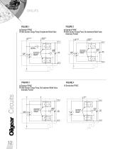
Standard PVWC With Gerotor Charge Pump & Implement Relief Valve Standard PVWC With Gerotor Charge Pump, No Implement Relief Valve (Externally Ported) I Standard PVWC I Gerotorless PVWC I With Gerotor Charge Pump, No Implement Relief Valve (Internally Ported)
Open the catalog to page 12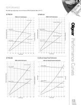
The following single pump curves are based on ISO 46 hydraulic fluid at 125° F.
Open the catalog to page 13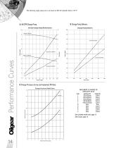
The following single pump curves are based on ISO 46 hydraulic fluid at 125° F. Performance Curves .64 CIPR Charge Pump Charge Pump Delivery Charge Pressure Curve and Implement RV Data IMPLEMENT & CHARGE RV CIRCUITRY DATA Code Implement RV Charge RV J 725 psi (50 bar) Curve A F 913 psi (63 bar) Curve A E 913 psi (63 bar) Curve B K 1160 psi (80 bar) Curve A L 1450 psi (100 bar) Curve A N None None G None Curve A B None Curve B H None Curve A A None Curve B See complete model code, page 15. See Circuits, page 12.
Open the catalog to page 14All Oilgear catalogs and technical brochures
 Transfer Barrier
4 Pages
 Screw-In Valves
4 Pages
 Transfer Barrier Technology
4 Pages
 C Pumps
4 Pages
 Pump Line
1 Page
 PVV Open Loop Pumps
24 Pages
 PVWW Pump
24 Pages
 PVK 140, 270 & 370 Pump
12 Pages
 PVG pump
28 Pages
 PVM Pump
24 Pages
 D and DN Pumps
2 Pages
 PVL pump
20 Pages


Archived catalogs
 VDC Series
12 Pages
 FS Flow Switches Sales
21 Pages
 MFW, MVW Fixed & Variable Motors
16 Pages