

PVW VV (A Frame) - EPC Wiring & Setup

PVW VV (A Frame) - EPC Wiring & Setup
- Pump Rotation: Designed for clockwise (CW) or counter-clockwise (CCW) rotation.
- LVDT Location: Determined by pump design and mounting preferences, with options for left hand side facing shaft (LHSFS), right hand side facing shaft (RHSFS), or top.
- Port of Delivery: Pumps can be one-way, neutral to 'A' or 'B' port, or two-way (bi-directional) 'A' to neutral to 'B'.
- Polarity (Command): Commands can be current or voltage, with assumed plus (+) voltage for 'A' port delivery.
- Polarity (LVDT): Determined by control/LVDT location and wiring, ensuring command and feedback cancel each other.
- Polarity, Module (Current): Affects servo valve pilot flow and pump 'Port of Delivery'.
- Dither (Output Current): Provides a 200 Hz current pulse to prevent servo valve sticking.
- Current Limit: Matches electrical maximum current output to servo valve design limit.
- LVDT Feedback Gain: Matches electrical feedback signals to pump stroke range.
- LVDT Feedback Offset: Matches feedback signals to pump minimum flow, with initial settings assuming ideal conditions.
- Stroke Controller Gain: Sets pump response time and accuracy.
- Initial calibration values are provided but may need optimization for specific applications.
- Improper wiring or calibration can lead to loss of control, improper operation, or damage.
- Contact Oilgear for cross-referencing model codes with 'L' or serial numbers.
- Access additional technical documents for flow control and user manual via the Oilgear website.
- Servo valve is mounted on top.
- LVDT is rated for +/- 0.50 inch stroke, while the pump is rated at +/- 0.462 inch stroke.
Catalog excerpts
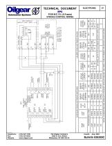
The Oilgear Company 2300 S. 51st. Street Milwaukee, WI USA 53219 ANALOG INPUT 4 POLARITY (LVDT) 845 NORMAL INVERT INVERT INVERT ANALOG INPUT 1 POLARITY COMMAND 852 NORMAL NORMAL NORMAL NORMAL DITHER OUTPUT CURRENT ANALOG INPUT 4 (LVDT FB) (GAIN) ANALOG INPUT 4 (LVDT FB) (OFFSET) STROKE CONTROL GAIN OPTIONAL ENTRY FOR CUSTOMER SPECIFIC APPLICATION MODULE CURRENT LIMIT MODULE POLARITY CURRENT CALIBRATIONS (SOFTWARE VALUES) * INITIAL CALIBRATIONS ARE ADEQUATE FOR MOST APPLICATIONS BUT MAY NEED TO BE OPTIMIZED FOR SPECIFIC APPLICATIONS PROGRAM MENU ITEMS CONFIGURATIONS (SOFTWARE SWITCHES) STROKE CONTROL WIRING
Open the catalog to page 1
TECHNICAL DOCUMENT STROKE CONTROL WIRING General Notes: This document references schematic wiring standards and software configurations/calibrations required to operate a specific pump, utilizing the Oilgear EPC amplifier. The pump is identified by a partial model code. Complete model codes are defined in pump bulletins. “L” (list) numbers or serial numbers may also identify pumps. Contact the Oilgear Company to cross reference “L” and serial numbers to model codes. Reference Technical Document 836261 for the “Flow Control Program” and Technical Document 836260 for the EPC “User Manual”. Both...
Open the catalog to page 2All Oilgear catalogs and technical brochures
 Transfer Barrier
4 Pages
 Screw-In Valves
4 Pages
 Transfer Barrier Technology
4 Pages
 C Pumps
4 Pages
 Pump Line
1 Page
 PVV Open Loop Pumps
24 Pages
 PVWW Pump
24 Pages
 PVK 140, 270 & 370 Pump
12 Pages
 PVWC 011, 014, 022 Pump
16 Pages
 PVG pump
28 Pages
 PVM Pump
24 Pages
 D and DN Pumps
2 Pages
 PVL pump
20 Pages


Archived catalogs
 VDC Series
12 Pages
 FS Flow Switches Sales
21 Pages
 MFW, MVW Fixed & Variable Motors
16 Pages
- Industrial pump
- Pump with electric motor
- Stationary pump
- Seawater pump
- Control valve
- Compact pump
- Flap valve
- Check valve
- Electric valve
- Directional control valve
- Piston pump
- Hydraulic pump
- Standard valve
- Hydraulic valve
- Hydraulic directional control valve
- Hydraulic piston pump
- Spool hydraulic directional control valve
- In-line valve