Catalog excerpts

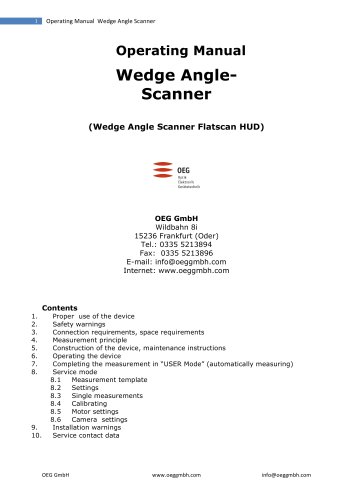
1 Operating Manual Wedge Angle Scanner Operating Manual Wedge Angle-Scanner (Wedge Angle Scanner Flatscan HUD) OEG GmbH Wildbahn 8i 15236 Frankfurt (Oder) Tel.: 0335 5213894 Fax: 0335 5213896 E-mail: info@oeggmbh.com Internet: www.oeggmbh.com 3. Connection requirements, space requirements 5. Construction of the device, maintenance instructions 7. Completing the measurement in "USER Mode" (automatically measuring) 10. Service contact data
Open the catalog to page 1
Operating Manual Wedge Angle Scanner 1. Proper Use of the Device The device wedge angle scanner serves only to measure the course of a wedge error on glass plates, especially automobile front windshields with the maximum dimensions: - Length 1600mm - Height 1000mm - Thickness 10mm. - The mass of the sample may not exceed 25kg. 2. Safety Warnings Emergency stop: The emergency stop switch must always remain accessible and may not be removed. The emergency stop switch cuts off the electricity supply for the stepper motor control. This function may not be altered. Motor power/travel speeds: The...
Open the catalog to page 2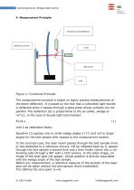
Figure 1: Functional Principle The measurement principle is based on highly precise measurements of the beam deflection. It is based on the fact that a collimated light bundle is deflected when it passes through a glass plate whose surfaces are not parallel. The deflection (δ) is proportional to the so-called „wedge error“(ε). In the case of double light transmission: δ≈2k ε with k as calibration factor. Equation (1) applies only to small wedge angles (<1°) and not to larger angles for the test sample with respect to the measurement system. In the concrete case, the laser beam passes...
Open the catalog to page 3
Operating Manual Wedge Angle Scanner Optik Elektronik Geratetechnik Attention! The calibration value, that is the proportionality k from the equation (1) for the wedge angle measurement depends on the refractive index of the glass and/or layer system of an automobile windshield. If precise absolute values of the wedge are demanded, theoretically it needs to be re-calibrated for every type of glass. If you are only interested in small fluctuations in wedge angles, you can calibrate using a standard glass since in that case small differences in the refractive index of the various types of...
Open the catalog to page 4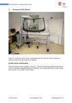
Figure 2: Structure of the front windshield scanner with the linear advancers, sample holder and automobile windshield Profile frame construction One can see the linear guides in Figure 2. This has the advantage that the device can be completely disassembled for transport and reassembled with relative ease and remains very stable mechanically.
Open the catalog to page 5
Specimen holder Figure 3: Specimen holder consisting of two plastic blocks with a nut, a stop and two outer supports on which it is leaned (only visible in Figure 1) The two plastic blocks and the stop will determine the position of the automobile windshield with respect to the portal system. All components of the specimen holder can be moved and fixed. Suggestion: The resting blocks for all types of automobile windshields should remain in the same position. The adjustment to the size of the windshield is then affected by the position of the stop. In this way the middle of the windshield...
Open the catalog to page 6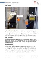
Laser Module Figure 4: Laser Assembly Group The intensity of the laser can be regulated (potentiometer on the back). Since the regulator range is not adequate, the beam will be further weakened by a polarisation filter during measurement. The filter can however be moved out of the beam path for purposes of adjustment so that the laser spot can be seen on a screen (paper). With the polarisation filter the laser spot is practically invisible. Beam adjustment The beam splitter plate will be mounted on a platform with an adjustable angle. Without a test specimen (“measurement in the air”), the...
Open the catalog to page 7
Operating Manual Wedge Angle Scanner Camera This is a CCD camera with a USB interface. Connection lines - The LSTEP control device is connected to the PC with the serial interface COM1. - The power supply for the LSTEP goes through the emergency stop switch - One line from each step motor goes to the control device. They are labelled. - The camera is supplied with power through the USB interface. - The laser is supplied with 12V DC (separate plug-in power supply) 6. Putting the Device into Operation Remove all objects from the measurement device that can restrict the portal's range of...
Open the catalog to page 8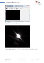
Figure 5: Program start in user mode Figure 6: Incorrect! Laser spot overshot. Diffraction effects are clearly visible.
Open the catalog to page 9
Figure 7: Correct! Diffraction effects are hardly visible. In spite of this the laser spot is visible as a bright spot. The operator will be asked to select a suitable measurement program for the windshield from a list. After the automobile windshield has been correctly positioned and the HUD and/or PVB number is typed in, the measurement procedure can be initiated with the “F4 Start”. The measurement begins with a reference measurement. Then the section of the automobile windshield selected in the background will be scanned. The measurement program can include several scanning ranges...
Open the catalog to page 10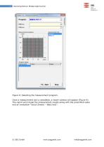
Operating Manual Wedge Angle Scanner Gravity Center list: Measurement progress: Program status: Gravty Center | Acton
Open the catalog to page 11
Operating Manual Wedge Angle Scanner OEG Optik Elektronik Geratetechnik WEDGE ANGLE MEASUREMENT REPORT GUARDIAN Company: Guardian Automotive Europe OEG Wedge Angle Scanner VI .0 GLOBAL MEASUREMENT LOCAL MEASUREMENT Average Standard Deviation: Min Standard Deviation: Peak to valley: Distance Min to Max: Peak to valley: Distance Min to Max: GLOBAL RESULT LOCAL RESULT Angle [mrad] Global Average- Figure 9: Protocol window (report). © OEG GmbH www.oeggmbh.com info@oeggmbh.com
Open the catalog to page 12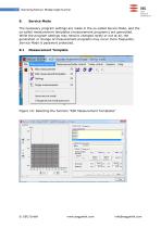
Service Mode The necessary program settings are made in the so-called Sevice Mode, and the so-called measurement templates (measurement programs) are generated. While the program settings may need to changed rarely or not at all, the generation or change of measurement programs may occur more frequently. Service Mode is password protected. 8.1 Measurement Template Figure 10: Selecting the function “Edit Measurement Templates”
Open the catalog to page 13All OEG catalogs and technical brochures
-
RTM
2 Pages
-
ELCOWIN & ELCOLEVEL
2 Pages
-
GPM2
2 Pages
-
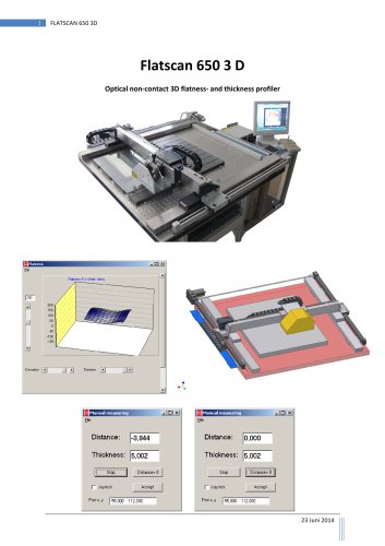
Flatscan 650 3D
7 Pages
-
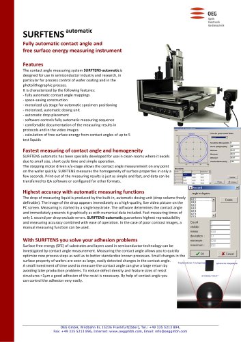
SURFTENS automatic
2 Pages
-
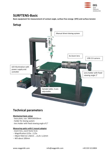
SURFTENS‐Basic
2 Pages
-
OPTICAL HEIGHT GAUGE OHM 150
2 Pages
-
MTF Master 200
2 Pages

