

- Products
- Catalogs
- News & Trends
- Exhibitions
Flatscan 650 3D
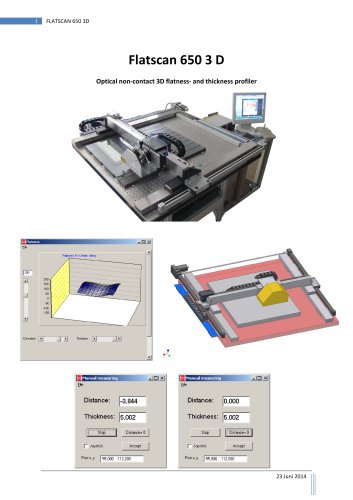
Flatscan 650 3D
The Flatscan 650 3D is an optical non-contact profiler used to measure the thickness and flatness of glass surfaces. It operates on a trigonometric principle using a laser line projected near the glass surface, with reflections captured by a CCD chip. The device measures thickness from 1.5 mm to 5 mm with a resolution of 0.001 mm and flatness up to 1 mm with the same resolution. Calibration is necessary for precise measurements, especially when different types of glass are used.
Device Construction
The Flatscan 650 is constructed with a lightweight aluminum profile and features air bearing rails for precise flatness measurements. It includes a plinth with vibration dampers and a breadboard for sample placement. The CAS sensor is manually adjustable for height, and the device requires regulated air pressure and step-motor control for operation.
Electrical and Pneumatic Connections
The device operates at 230V and requires an air pressure of 5 Bar. It connects to a PC via a serial interface, and the CAS sensor is powered by 12V DC from the PC. Pneumatic connections use a 6 mm diameter plastic pressure hose.
Measurement Procedures
Manual Measurement: This basic form allows for function checks and adjustments using a joystick to select positions.
Automatic Measurement: The primary function for surface measurement, scanning the glass plate in a grid pattern to provide thickness and flatness data. The process involves setting up a measurement pattern and using software to analyze results.
Data and Maintenance
Measurement results can be displayed as graphics, which can be copied, printed, and saved. Regular maintenance includes cleaning stainless rails and monitoring air filters. The device requires minimal maintenance beyond these tasks.
Catalog excerpts
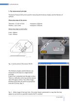
1. The measurement principle The device Flatscan 650 can be used for measuring the thickness of glass and the flatness of surfaces. Measuring range of the sensor: Thickness: 1.5 mm to 5mm resolution: 0.001mm Flatness: up to 1mm resolution: 0.001mm Measuring range: portal facility: X axis: 550mm Y axis: 650mm Fig. 1: Construction of the sensor CAS 45 The thickness of glass and the flatness are measured on the basis of a trigonometric principle. A laser line is projected near the glass surface. There is a reflection at the top and the bottom ...
Open the catalog to page 2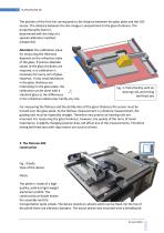
The position of the first line corresponds to the distance between the glass plate and the CAS sensor. The distance between the line images is proportional to the glass thickness. The proportionality factor is determined with the help of a special calibration method. (chapter10). Attention: The calibration value for measuring the thickness depends on the refractive index of the glass. If precise absolute values of the glass thickness are required, a re‐calibration is necessary for every sort of glass. However, if only small deviations in the glass thickness are interesting on the glass plate, the ...
Open the catalog to page 3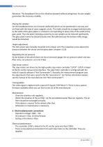
Attention: The breadboard lies on the vibration dampers without being fixed. Its own weight guarantees the necessary stability. Placing the samples On the breadboard there are slid steel shafts (H6) which can be positioned in any way and are fixed with the help of some magnetic sticks. The shafts should be arranged symmetrically to the width of the glass plates in a distance corresponding to about 75% of the width of the glass plate. Thus the plate’s bending caused by its own weight can be reduced significantly. The glass plate cannot be placed directly onto the table because the bottom reflex image ...
Open the catalog to page 4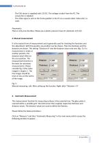
Pneumatics There is only one interface. Please use a plastic pressure hose of a diameter of 6 mm. 4. Manual measurement It is the easiest form of measurement and is generally used for checking the functions and the adjustment. With the joystick, any position can be chosen. Then the thickness and the distance are shown. The setting “Distance=0” sets the distance value onto zero (fig.: 5). If a measurement is made at another position, the distance value refers to the zero position. This measurement function is the basis for automatic measurements. Please consider fig. 2 (the video ...
Open the catalog to page 5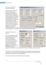
Fig. 6: First window for the automatic measurement The form shows the look of the measurement pattern, the dimensions of the sample and which mathematic operations should be used for analysing the measurement results. The window can only be edited in the service mode (chapter 9). A sensible file must be loaded which contains the prepared measurement task corresponding to the sample. The buttons are active. They can be used to check if the measurement template is correct and if the sample strikes the stops. If everything is okay, click on “Accept measuring procedure“ so that the actual measurement window appears. (Bild 7). ...
Open the catalog to page 6
Flatness diagram, thickness diagram Here you can call up simple graphics for just measured samples. The graphics can be copied, printed and saved. Please consider that measurement values are saved, no bitmaps. Earlier saved measurement values can be loaded up and displayed. Fig. 12: Example of a flatness graphic Attention: If there are very many measurement values, the data set is reduced onto maximally 100 x 100 measurement values with the help of an interpolation method. The same applies to saving the data. OEG GmbH Wild
Open the catalog to page 7All OEG catalogs and technical brochures
 RTM
RTM2 Pages
 ELCOWIN & ELCOLEVEL
2 Pages
 GPM2
GPM22 Pages
 SURFTENS automatic
2 Pages
 SURFTENS‐Basic
2 Pages
 OPTICAL HEIGHT GAUGE OHM 150
2 Pages
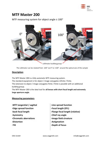 MTF Master 200
2 Pages

- Measuring device
- Measuring machine
- Process software
- Windows software
- Microscope
- Optical microscope
- Measurement software
- Quality software
- Automatic test kit
- Automatic measurement system
- Inspection microscope
- Optical measurement system
- Automatic measuring module
- Geometry measuring instrument
- Laboratory measuring instrument
- Laser measuring machine
- Diameter measurement system
- Upright microscope
- Optical gauge
- CAPM software