
- Catalogs
- ODU GmbH & Co. KG
- ODU-MAC® Silver-Line / ODU DOCK Silver-Line – Catalog


- Company
- Products
- Catalogs
- News & Trends
- Exhibitions
ODU-MAC® Silver-Line / ODU DOCK Silver-Line – Catalog
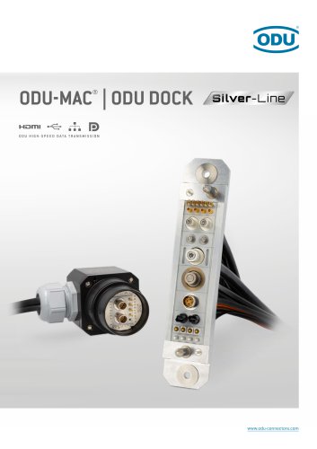
ODU-MAC® Silver-Line / ODU DOCK Silver-Line – Catalog
- Robust design with high reliability and vibration resistance.
- Capable of over 100,000 mating cycles with stable low contact resistance.
- Offers a wide variety of transmission modules and compact solution possibilities.
- Ensures maximum packing density and supports blind mating.
- Medical, Industrial, Test and Measurement, Military, Security and Communication, Mass Interconnect, Automotive.
- Connectors must be mated/unmated without current load.
- Compliant with IEC 61984-2008 and certified according to UL 1977/CSA C 22.2 no. 182.3.
- Tested to MIL/SAE/EIA standards.
- Modules should be purchased assembled with frames to prevent assembly errors.
- Use ODU tools and follow current assembly instructions available online.
- ODU connectors have a unique contact arrangement but meet electrical specifications of standard protocols.
- ODU-MAC® is a modular solution for varied applications, offering automatic docking and individual connection configurations.
- Includes a web configurator for custom solutions.
- Detailed system requirements and tolerances are provided for optimal performance.
- Guidance on selecting frames for automatic docking is available.
- 100,000 mating cycles for reduced total cost of ownership.
- Rigid aluminum frames for automatic docking.
- High modularity for flexibility and space-saving due to high contact density.
- ODU-MAC® S+: Standard solution for docking tasks with optional PE transmission. It supports ≥ 100,000 mating cycles and offers tolerance compensation with axial play of 0.4 mm and radial play of ± 1.2 mm.
- ODU-MAC® P+: Reinforced frame design for high mechanical requirements. It is recommended for modules with contact diameter > 5 mm or frame length > 40 units and mandatory for contact diameter > 8 mm. It supports ≥ 100,000 mating cycles with axial play of 1 mm and radial play of ± 2.5 mm.
- ODU-MAC® P4+: Similar to P+ but with extended tolerance compensation, offering radial play of ± 4.0 mm.
- ODU-MAC® L: Features higher tolerance compensation and reinforced guiding bushes with extended guiding pins. It supports ≥ 100,000 mating cycles with axial play of 0.4 mm and radial play of ± 1.2 mm.
- ODU-MAC® M+: Compact design with minimal space requirements, offering axial play of 0.4 mm and radial play of ± 0.6 mm.
- ODU-MAC® S: Standard solution with axial play of 0.2 mm and radial play of ± 0.6 mm, supporting ≥ 100,000 mating cycles.
- ODU-MAC® QCH: Designed for maximized mating cycle capabilities and minimized maintenance downtime. It consists of interchangeable parts to facilitate easy maintenance.
Technical Data
The document provides detailed technical data for each model, including tolerance compensation, floating support, and optional PE transmission. It also includes part numbers for pin and socket frames, and instructions for selecting the number of units.
Recommendations and Compatibility
The document recommends specific models based on contact diameter and frame length requirements. It also highlights compatibility issues, such as the non-compatibility of certain frames with the ODU-MAC® S frame.
Contact Information
For further inquiries, the document provides contact information for the sales team at [email protected].
Specifications: The document outlines various modules available for the ODU-MAC® QCH, including signal, power, high-current, high-voltage, RF-signal (coax), compressed air and fluid modules, and fiber optic modules. Each module is described with its contact diameter, units, operating voltage, rated impulse voltage, maximum continuous current, degree of pollution, and mating cycles.
Procedures: The document suggests that only interchange parts need replacement during maintenance, while base parts remain assembled. This reduces the total cost of ownership and saves time.
Standards and Recommendations: The document mentions compliance with IEC 60664-1:2020 standards for pollution degree and provides recommendations for stripping lengths in assembly instructions.
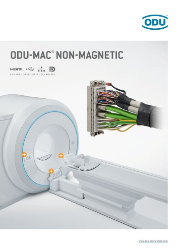
Key Features: The ODU-MAC® QCH system supports high contact density, last-mate-first-break functionality, and offers non-magnetic versions on request. It also includes options for grounding kits and strain relief housing.
Technical Data: The document provides technical data for various components, including tolerance compensation, material specifications, operating temperature range, and protection class options.
Accessories: Accessories such as cable clamps and locknuts are available, with options for customer-specific logos on the housing.
- Voltage Information: According to IEC 60664-1:2020 and MIL, EIA-364-20F:2019 standards, the operating voltage varies from 16 V to 500 V, with rated impulse voltages up to 3,000 V. The degree of pollution ranges from 2 to 3, with clearance and creepage distances specified for different modules.
- Mechanical Data: The modules have varying total mating and sliding forces, with contact diameters ranging from 0.7 mm to 2.41 mm. Operating temperatures are between -40 °C and +125 °C, and mating cycles are ≥ 100,000.
- Materials: Insulators are made from thermoplastic fiber glass reinforced according to UL 94. Contacts are made from Cu alloy, with plating options including Au over Ni and Ag.
Modules and Contacts
- Module Configurations: Modules are available with different numbers of contacts (e.g., 4, 5, 6, 10), each with specific part numbers and configurations for pin and socket contacts.
- Contact Specifications: Contacts have varying current-carrying capacities, with single contacts supporting up to 41 A. Contact resistance is specified in mΩ for different configurations.
- Last-Mate-First-Break Function: This function is supported by using short and long contacts, ensuring reliable connections.
Technical Notes
- Current Load Information: The current load is valid for single contacts or fully equipped modules, with reductions recommended for connector systems according to DIN VDE 0298-4:2023-06.
- Compatibility: Modules with turned contacts are not compatible with stamped contacts or modules.
- Crimp Information: Detailed crimping instructions are provided on specific pages for proper assembly.
Tools and Accessories
- Removal Tools: Various tools are available for removing assembled and unassembled contacts, with specific part numbers provided for each tool type.
The document provides detailed specifications for various modules and contacts, focusing on current load, voltage, and mechanical data. The current load information is applicable for single contacts or fully equipped modules, with reductions required for connector systems as per DIN VDE 0298-4:2023-06. Voltage specifications are provided according to IEC 60664-1:2020 and MIL, ANSI / EIA-364-20F:2019 standards, with operating voltages ranging from 200 V to 2,500 V and rated impulse voltages up to 10,000 V. Mechanical data includes total mating and sliding forces, contact diameters, operating temperatures, and mating cycles.
Materials and Construction
The modules are constructed using thermoplastic fiber glass reinforced insulators, copper alloy contact bodies, and various contact spring materials such as CuBe and CuSn alloys. Contact plating is typically silver or gold over nickel.
Assembly and Tools
Specific tools are required for assembly and disassembly, including torque wrenches and Torx bits. Part numbers for these tools are provided, and an overview of all tools is available from page 191.
Module Types and Capacities
The document details different module types, including ODU LAMTAC® and LAMTAC® Flex, with varying contact diameters and current-carrying capacities. Modules are designed for high-current applications, with some capable of handling up to 225 A. The document also includes information on protective grounding modules and their specifications.
Technical Notes and Recommendations
The document emphasizes the importance of using specific frames (ODU-MAC® P+ or P4+) due to high mating forces and cable cross sections. It also provides guidance on crimping and the positioning of modules within frames. The document advises checking cable space requirements when using housings and highlights the need for compliance with various standards for conductor cross-sections and protective grounding.
- Socket Contacts: Various models are listed with specifications such as part numbers, compatible cable types (e.g., RG 178, RG 174), and dimensions.
- Pin Contacts: Details include part numbers, characteristic impedance, frequency range, and cable compatibility.
- Crimping Tools: Specific tools for shielding sleeves and other applications are identified by part numbers.
- Frequency Range: 0 – 3.0 GHz for high-frequency applications.
- Insulation Resistance: Greater than 100 GΩ.
- Voltage Ratings: Operating voltage up to 500 V, with rated impulse voltage at 4.0 kV.
- Mechanical Properties: Operating temperature ranges from −40 °C to +125 °C, with mating cycles ≥ 100,000.
- Insulator: Thermoplastic fiberglass reinforced according to UL 94.
- Contact Body: Made from copper alloy, with specific plating for center and outer contacts.
- Crimping information and testing standards are referenced, including SMPTE and IEC standards.
- Special handling notes for pre-stressed contacts and vacuum models.
- Operating Pressure: Up to 25 bar for fluid models, with specific flow rate diagrams provided.
- Termination Types: Various fittings and connections are detailed, including push-in and nipple fittings.
- Regular service intervals are suggested for maintaining specified mating cycles.
- Not suitable for use with flammable or explosive gases or liquids.
- Connectors are designed for data rates up to 48 Gbit/s, supporting systems like Ethernet, USB, HDMI, and DisplayPort.
- Contact arrangements vary from 2 to 30 contacts, with specific configurations for different data transfer standards such as CAT5, CAT6A, and USB 3.2 Gen 1x1.
- Materials used include thermoplastic fiberglass reinforced insulators, with a CTI value of 600.
- Assembly and configuration instructions are provided for high-speed connectors, including available crimp contacts on request.
- Tools for insertion and removal of contacts are specified, with part numbers for easy reference.
- Operating temperature range is from -40°C to +125°C.
- Mating cycles are rated at ≥ 10,000 for ODU Turntac® and ≥ 60,000 for ODU Springtac® connectors.
- Mechanical data includes total mating and sliding forces, with average values provided per module.
- Ensure compatibility with housing space requirements when applying connectors.
- For optimal performance, select inserts based on the specific data rate requirements of the application.
The document provides detailed information about the ODU DOCK system, which includes insulators and contacts. Optional dummy contacts can be ordered. The ODU-MAC® adapter enhances modular options for size 3, allowing for the transmission of bus signals, data, light waves, and media such as air and fluids. Users can configure modules to meet specific application needs, with part numbers available on page 52.
This technology reduces servicing time by allowing easy replacement of exchange components while base parts remain cabled, significantly increasing the number of mating cycles. More details can be found on page 139.
Cable clamps are available in metal or plastic, with or without EMC protection. Further information is available on page 194.
The document includes detailed tables of contact specifications for sizes 1, 2, and 3, including conductor cross-section, contact diameter, material surface, and maximum nominal current. Users are advised to refer to derating charts on page 204 when selecting conductor cross-sections.
The technical data section provides information on material, protection class, operating temperature, and other mechanical data for different sizes and materials of the ODU DOCK system. The document also includes part numbers for various components such as socket and pin pieces, insulators, and dummy contacts.
The document provides detailed technical specifications for crimp contacts and related components. It includes voltage information, material housing options (plastic and metal), and operating conditions. The operating voltage ranges from 400 V to 1,600 V, with rated impulse voltages between 3,000 V and 8,000 V. The degree of pollution is specified as 2 or 3, depending on the material.
Mechanical Data
The mechanical data section outlines the total mating force (average 57-79 N) and sliding force (average 34-50 N). The operating temperature range is from -40 °C to +120 °C, and the components are designed for ≥ 100,000 mating cycles.
Materials
The materials used include PBT-fiberglass reinforced insulators, Cu alloy contact bodies, CuSn alloy contact springs, and Au or Ag contact plating. Grounding is provided via the insulator geometry, eliminating the need for extra grounding contacts.
Tools and Assembly
Crimping tools and assembly/removal tools are referenced, with specific page numbers provided for further details.
Component Descriptions
The document lists various parts with their part numbers, contact diameters, conductor cross-sections, nominal currents, and contact resistances. It includes both socket and pin contacts, with specific details on dummy contacts and grounding pin contacts.
Housing and Protection
The housing options include plastic and aluminum, with protection classes IP40 and IP65. The document specifies the operating temperature and cable exit options (straight and right-angled). EMC protection is optional for certain configurations.
Contact Inserts
The contact inserts are detailed with contact diameters and conductor cross-sections. The document provides guidelines for determining current-carrying capacity, referencing relevant IEC standards.
Diagrams and Measurements
The document includes diagrams with precise measurements for various components, ensuring accurate assembly and compatibility.
1. Voltage Information: The document provides voltage specifications for different materials, with operating voltages ranging from 40 V to 800 V and rated impulse voltages from 2,500 V to 5,000 V. The degree of pollution varies between 2 and 3.
2. Mechanical Data: The connectors have a total mating force ranging from 162 N to 237 N and a sliding force from 100 N to 153 N. They are designed to operate in temperatures from -40 °C to +120 °C and support over 100,000 mating cycles.
3. Materials: The insulator is made of PBT-fiberglass reinforced according to UL 94, with contact bodies made of Cu alloy and contact springs of CuSn alloy. Contact plating is silver (Ag).
Components and Tools
1. Insulator and Contacts: Various part numbers are provided for insulator sockets, pins, and dummy contacts. The document specifies contact diameters and conductor cross-sections.
2. Crimping and Assembly Tools: References to pages for crimping tools (page 183) and assembly/removal tools (page 192) are included.
Design and Configuration
1. ODU Dock Size 3: The document details the technical data for ODU Dock Size 3 connectors, including voltage, mechanical data, and materials.
2. Quick Change Head: Describes the quick change head system with base parts equipped with crimp contacts, allowing for easy service and replacement of interchange parts.
3. Flexible Circular Connectors: The document discusses the use of ODU-MAC® modules for modular circular connectors, compatible with ODU DOCK Silver-Line size 3 housings, allowing for customizable configurations.
Recommendations and Standards
1. Standards Compliance: The document references compliance with IEC 60664-1:2020 and IEC 60512-5-1:2002 standards.
2. Design Recommendations: Suggestions for using specific configurations and materials for optimal performance are provided.
This document provides detailed information on ODU-MAC® modules, focusing on termination technology, tools, and accessories for crimping processes. It includes specifications, procedures, and recommendations for effective use of crimping tools and techniques.
Specifications
The document outlines three contact termination technologies: crimp, solder cup, and PCB. Crimping is highlighted as a secure, durable, and corrosion-free method, suitable for various conductor diameters. Specific tools are recommended for different cross-sections, ensuring error-free crimping.
Crimping Tools
Various crimping tools are detailed, including mechanical hexagonal hand crimping tools, 8-point crimping tools, and hydraulic crimping tools. Each tool is specified with part numbers and suitable contact diameters. The document emphasizes the importance of using ODU-recommended tools for optimal results.
Tensile Strength and Standards
A tensile strength diagram is provided, illustrating the relationship between conductor cross-section and tensile strength, adhering to IEC 60352-2:2013 standards. The document stresses the importance of observing specified mating and sliding forces to prevent damage.
Recommendations
For error-free crimping, it is recommended to use the correct bore diameter and ODU-recommended tools. The document advises on testing electrical continuity following assembly and highlights the use of suitable test adapters.
Additional Information
Further details on crimping jaws, positioners, and specific part numbers for various tools are provided. The document also includes guidelines for stripping lengths and adjustment dimensions for different contact diameters.
Conclusion
This document serves as a comprehensive guide for selecting and using crimping tools and techniques, ensuring secure and reliable connections in ODU-MAC® modules.
The document outlines the specifications for finely stranded conductor designs according to DIN EN IEC 60228 VDE 0295:2024-12 class 5 and AWG ASTM B258:2018. It includes details on tools and accessories, particularly torque wrenches and bits, with specific part numbers and recommended tightening torques.
Tools and Accessories:
The document provides a comprehensive list of tools and accessories, including torque wrenches, bits, and assembly aids. Each tool is associated with a part number and recommended torque settings. The tools are designed for specific tasks such as mounting spindle coding, screwing rails, and mounting grounding sockets and pins.
Assembly Aid:
Details are provided for assembly aids like insertion tools for contacts with flexible conductors. The document emphasizes that removal and assembly of contacts should only be done with ODU tools.
Technical Data:
The document includes technical data for locknuts and cable clamps, specifying materials, protection classes, and temperature ranges. It also provides part numbers and dimensions for various components.
Service Kit:
A service kit for ODU SPRINGTAC® and ODU LAMTAC® contacts is described, which includes lubrication and cleaning tools to improve mechanical properties and reduce wear.
Cleaning Information:
Recommendations for cleaning connectors are provided, including the use of specific cleaning agents and the importance of ensuring connectors are dry before use.
Technical Information:
The document explains international protection classes according to IEC 60529:2013, detailing protection against solid objects and water ingress. It also covers safety requirements, tests, and voltage data according to IEC 61984:2008.
The document outlines the importance of adhering to standards such as IEC 61984:2008 and DIN EN 61984 VDE 0627:2009-11 for protection against electric shock and touch protection. It emphasizes the need for customer-provided touch protection when using connectors without complete IP protection.
Assembly Recommendations:
It is recommended to purchase modules assembled with frames to avoid assembly errors. The use of ODU tools and adherence to current assembly instructions is emphasized.
Voltage Data and Insulation Coordination:
Voltage data is based on IEC 60664-1:2020 standards, which regulate clearance and creepage distances. The document explains the influence of pollution degree on insulation and the importance of considering product-specific standards.
Operating and Rated Voltage:
The document defines operating voltage as the manufacturer's specified voltage for a component. It also explains rated impulse voltage and its dependence on pollution degree and clearance distances.
Pollution Degree and Insulation:
Different pollution degrees are defined, affecting the insulation capacity of connectors. The document specifies the conditions under which different pollution degrees apply.
Wire Gauge and Current-Carrying Capacity:
The document provides a detailed table of American Wire Gauge (AWG) specifications, explaining the relationship between wire diameter, cross-section, and resistance. It also describes how current-carrying capacity is determined by measuring self-heating and ambient temperature effects.
Catalog excerpts
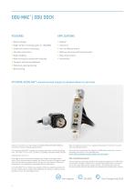
• Robust design • High number of mating cycles (> 100,000) • Stable low contact resistance • Vibration resistance • High reliability • Wide variety of transmission modules • Compact solution possibilities • Maximum packing density • Blind mating • Military, Security and Communication • Mass Interconnect ATTENTION: All ODU-MAC® connectors must only be (un)mated without current load. All shown connectors are according to IEC 61984-2008 (VDE 0627:2009-11); Only in exceptional cases we can supply individual parts. However, we cannot connectors without breaking capacity (COC). take any liability therefore....
Open the catalog to page 2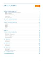
Clickable page numbers PRODUCT INFORMATION ODU-MAC® ODU-MAC® – AUTOMATIC DOCKING FRAMES FOR AUTOMATIC DOCKING PRODUCT INFORMATION ODU DOCK TOOLS AND ACCESSORIES TECHNICAL INFORMATION
Open the catalog to page 3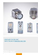
CONFIGURE THE ODU-MAC® SIMPLY ONLINE AT WWW.ODU-MAC.COM
Open the catalog to page 4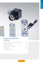
PRODUCTINFORMATION ODU-MAC®
Open the catalog to page 5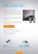
PRODUCT INFORMATION ODU-MAC® ODU-MAC® – A MODULAR ALL-ROUNDER FOR THE MOST VARIED APPLICATIONS THE INTELLIGENT WAY TO A CONSOLIDATED CONNECTION The ODU-MAC®’s flexible, modular design enables multiple connection types to be combined in just one connector. Whether signal, power, high-current, high-voltage, RF-signal (coax), high-speed data transmission, fiber optic and other media such as air or fluid – all types can be selected from the module and integrated into the consolidated connector solution. The connection options are just as versatile. Many options are available for a variety of applications,...
Open the catalog to page 6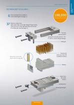
Various docking frames available in customizable lengths (see page 10) Mating cycles and more Modules to choose from: Signal, power, high-current, high-voltage, RF-signal (coax), media such as air or fluid, high-speed data transmission, PE and fiber optic (see from page 42) Pin frame (for pin contact) Optional PE connection on the S+ / M+ / P+ and P4+ versions with grounding kit Guiding pin Contacts with solder cup, crimp, PCB and SMA terminations Removable contacts with clip principle (see page 16) Socket frame (for socket contact) Guiding bushes Optional grounding kit PRODUCTINFORMATION ODU-MAC®...
Open the catalog to page 7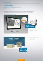
PRODUCT INFORMATION ODU-MAC® CONFIGURATOR Individual configuration of your ODU-MAC® Silver-Line connection With the ODU-MAC® configurator it’s possible to configure your connection simply according to your requirements. The configurator guides you through the different choices step by step and offers a lot of further information. CONFIGURE YOUR ODU-MAC® SILVER-LINE HERE: GO TO CONFIGURATOR www.odu-mac.com takes you directly to the ODU-MAC® configurator. Find a variety of videos explaining the functions of automatic docking and use cases of our ODU-MAC® Silver-Line on ODU’s vimeo channel. WATCH...
Open the catalog to page 8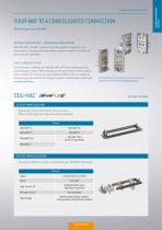
PRODUCT INFORMATION ODU-MAC' YOUR WAY TO A CONSOLIDATED CONNECTION How to configure your ODU-MAC®. INDIVIDUAL REQUIREMENTS - CONSOLIDATED CONFIGURATION With ODU-MAC®, we offer a modular connector system configured to your requirements. This means that you always receive the hybrid connection for your particular application. SELECT & REQUEST OFFERS You will receive a drawing and a detailed offer within one working day after submitting your request. When placing an order you will receive the complete article number for connections preassembled by ODU (contacts supplied as accompanying loose items)....
Open the catalog to page 9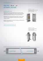
PRODUCT INFORMATION ODU-MAC® ODU-MAC® AUTOMATIC DOCKING. ODU-MAC® S+ (p. 26) Standard solution for docking tasks with optional PE transmission OVERVIEW OF DOCKING FRAMES ODU-MAC® Silver-Line is the best suitable solution for automatic docking. Choose from a variety of different frames, adjust the length individually and assemble the frame with the modules you need for your requirements. With ODU-MAC® you can always find the perfect solution. And if your requirements for a connection go beyond the standard solutions, we also offer customized solutions. ODU-MAC® can be configured for 3 to 60 units....
Open the catalog to page 10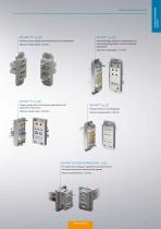
Reinforced frame design with extended tolerance compensation Frame with higher tolerance compensation and reinforced guiding bushes, as well as extended guiding pins ODU-MAC® M+ (p. 30) Compact design with minimal space requirements and optional PE transmission Standard solution for docking tasks ODU-MAC® QCH (QUICK CHANGE HEAD – p. 32) For maximized mating cycle capabilities (connector saver), minimized maintenance downtime and expense Tolerance compensation: ± 1.2 mm PRODUCTINFORMATION ODU-MAC® PRODUCT INFORMATIO
Open the catalog to page 11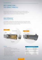
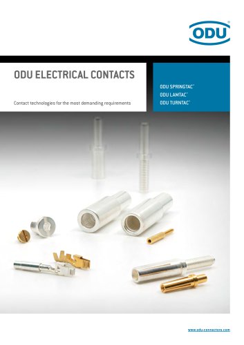
ODU contacts fulfill the highest quality standards and enable secure and reliable connections. ODU has the highest performance contact technologies at its disposal. Principally, a differentiation of machined contacts is made between lamella, springwire and slotted contacts. The socket side differs in architecture, whereas the pins are always based on a solid design. Contacts with springwire technology The ODU SPRINGTAC® is the most effective contact system on the market. Constant transfer is always guaranteed thanks to the large number of individual, independently flexible springwires. Even with...
Open the catalog to page 12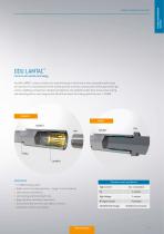
PRODUCT INFORMATION ODU-MAC' ODU LAMTAC® Contacts with lamella technology The ODU LAMTAC® contact consists of a machined body in which one or more stamped lamella strips are mounted. The individual bars of the lamella provide numerous contact points which guarantee high contact reliability and optimum conductive properties. The adapted contact force ensures low mating and demating forces, and a long service life with low wear. The mating cycles here are > 10,000. • High current-carrying capacity - surge current capacity • Low mating and demating forces • High vibration and shock resistance •...
Open the catalog to page 13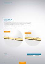
Contacts in slotted version The universal ODU TURNTAC® contact system combines the very best contact properties and high quality with economic prices. By means of the optimum guidance and assembly in the ODU-MAC® system, the longevity of 10,000 mating cycles and more can be achieved. The contact principle can even be used in dimensions as tiny as 0.3 mm in diameter. Depending on the variety of slotted contact, the connector systems offers two or four contact areas. • Economical solution • The smallest dimensions are possible • Individual contacts on request Standard contact principle for Shielded...
Open the catalog to page 14All ODU GmbH & Co. KG catalogs and technical brochures
 MINI‐MED®
8 Pages
 AMC® Threaded
16 Pages
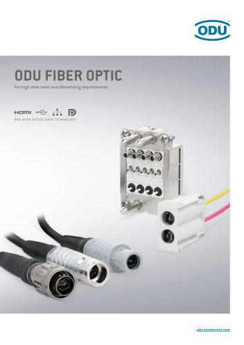 ODU Fiber Optic – Catalog
176 Pages
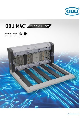 ODU-MAC® Black-Line – Catalog
74 Pages
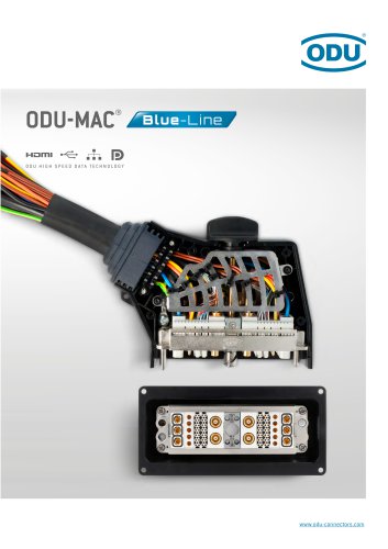 ODU-MAC® Blue-Line – Catalog
196 Pages
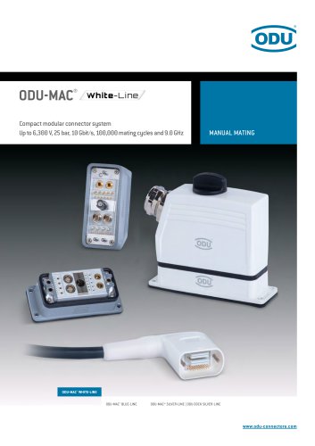 ODU-MAC® White-Line – Catalog
184 Pages
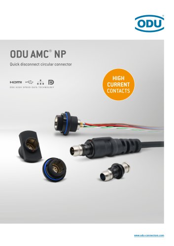 ODU AMC® NP – Catalog
52 Pages
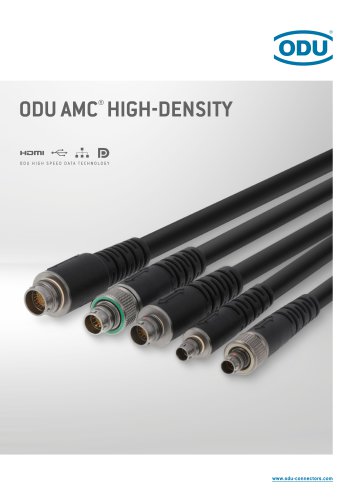 ODU AMC® High-Density – Catalog
56 Pages
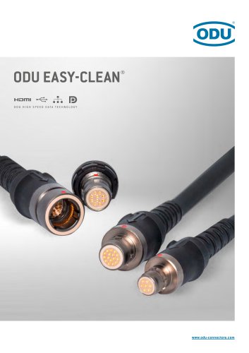 ODU AMC® Easy-Clean – Catalog
54 Pages
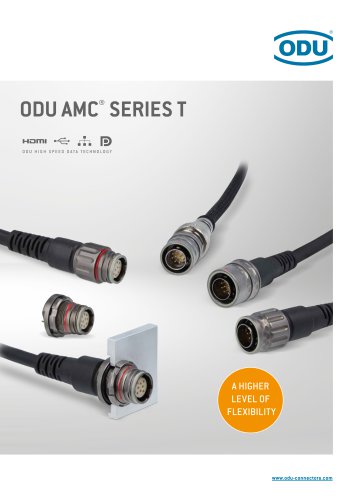 ODU AMC® Series T – Catalog
88 Pages
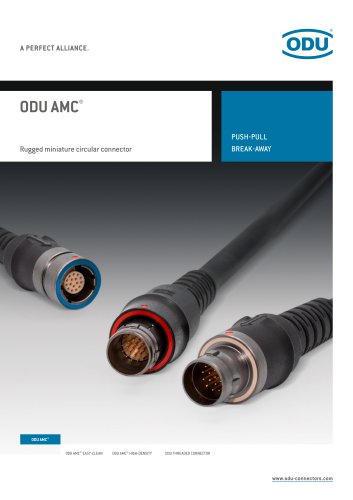 ODU AMC® – Catalog
76 Pages
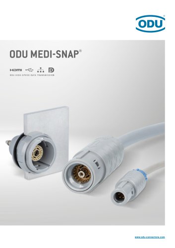 ODU MEDI-SNAP® – Catalog
126 Pages
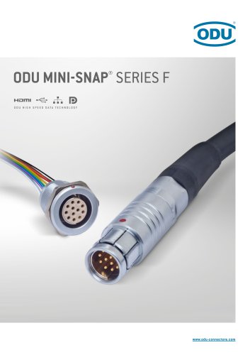 ODU MINI‐SNAP® Series F – Catalog
106 Pages
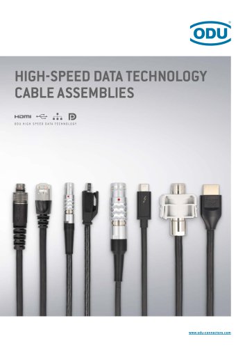
- ODU data connector
- ODU electrical power supply connector
- ODU metal connector
- ODU plastic connector
- ODU screw-in connector
- ODU industrial connector
- IP67 connector
- ODU rectangular connector
- Current connector
- Cable connector
- Straight connector
- Cable assembly
- RF connector
- Screw connector
- DIN connector
- Nickel-plated brass connector
- Multipole connector
- Voltage connector