- Catalogs
- ODOT Automation
- Remote I/O C Series
- Company
- Products
- Catalogs
- News & Trends
- Exhibitions
Remote I/O C Series
1 /376Pages

Remote I/O C Series
1 /376Pages
Catalog excerpts

User Manual http:// www.odotautomation.com
Open the catalog to page 1
Odot Automation System Co., Ltd. 2020-2 Copyright ©2020 Odot Automation all rights reserved http:// www.odotautomation.com
Open the catalog to page 2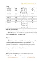
Ownership rights information Without the permission of the copyright owner,all or part of this document shall not be republished as a paper or electronic document. Disclaimer This document is only intended to assist the reader in using the products, and the company shall not be responsible for any loss or error caused by the use of the information in this document. The product and text described in this document are under constant development and refinement. Odot Automation System Co., Ltd. has the right to modify this document without notifying users. Software download Please log on the official...
Open the catalog to page 3
http:// www.odotautomation.com
Open the catalog to page 14
1 Product Overview Remote IO system consists of network adapter module and extended IO module. The network adapter module controls fieldbus communication and it realizes communication link with host station controller or host computer software. The extended IO module controls the connection with the input and output sensors in the field. At first the Input IO module collects the field signals and sends it to the network adapter through the internal bus. Secondly the controller reads and processing data from the adapter through the field bus, and it writes the output data into the network adapter,...
Open the catalog to page 15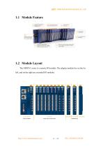
1.2 Module Layout The ODOT-C series is a remote I/O module. The adapter module lies on the far left, and on the right are extended I/O modules. http:// www.odotautomation.com
Open the catalog to page 16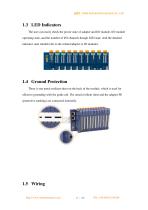
1.3 LED Indicators The user can easily check the power state of adapter and I/O module, I/O module operating state, and the number of I/O channels though LED state. And the detailed indicator state should refer to the related adapter or IO modules. 1.4 Ground Protection There is one metal resilient sheet on the back of the module, which is used for effective grounding with the guide rail. The metal resilient sheet and the adapter PE (protective earthing) are connected internally. 1.5 Wiring http:// www.odotautomation.com
Open the catalog to page 17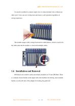
Use push-in method to connect single-wire or crimp terminal wires without any other tools. Users can save wiring time and ensure a safe operation regardless of wiring experience. The module equips with a wiring fixed end for cable harness, which is used to fix the cable when the IO module is wired with multiple cables. 1.6 Installation and Removal DIN-Rail Lock could be safely and reliably installed on 35 mm DIN-Rail. There is a manual closure buckle on the upper side of all modules for locking, and a manual buckle is on the left side of the adapter for locking the guide rail. http:// www.odotautomation.com...
Open the catalog to page 18
When the module is removed, it needs to manually unlock the guide rail on the upper side of the module. For the adapter module, you also need to unlock the left rail buckle counterclockwise. http:// www.odotautomation.com
Open the catalog to page 19
1.7 Installation Size Adapter size: 115*51.5*75mm 2 Network Adapter CN-8011 Modbus-RTU Network Adapter 1 Module Overview CN-8011 Modbus-RTU network adapter supports standard Modbus-RTU communication, it supports function code of 01/02/03/04/05/06/15/16/23, and this device could monitor the IO module communication state in real time. 2 Technical Parameter Adapter Hardware Parameter System Power Power Consumption Internal Bus Supply Current Isolation Power Supply Field Power Current http:// www.odotautomation.com Nominal:24Vdc, Range: 9-36Vdc Reverse Protection: YES 30mA@24Vdc Max:2.5A@5VDC System...
Open the catalog to page 20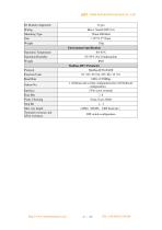
IO Modules Supported Wiring Mounting Type Operation Temperature Operation Humidity Protocol Function Code Baud Rate 2400~115200bps 1~63(Dial-code switch configuration),64~247(Software configuration) 5 Pin screw terminal Data Bits Parity Checking Stop Bit Max. bus length Terminal resistance and offset resistance http:// www.odotautomation.com 1,2 1200m(RS485,2400 baud rate) DIP switch configuration
Open the catalog to page 21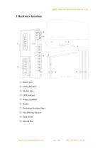
① RS485 port ② Config Interface ③ Module type ④ LED Indicator ⑤ Wiring Terminal ⑥ Buckle ⑦ Grounding Resilient Sheet ⑧ Fixed Wiring Harness ⑨ Field Power ⑩ Internal Bus http:// www.odotautomation.com
Open the catalog to page 22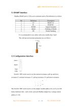
3.1 RS485 Interface Modbus RS485 port is 5 Pin screw terminals and its Pin definition is as below: Pin 1 2 3 4 5 Definition A+ BSGND Shield PE Description RS485 A+ RS485 BSignal Grounded Earthing of Shield Protect Earthing It is recommended to use cables with cores smaller than 1mm² . The cold-pressed terminal parameters are as follows: Switch1: DIP switch used to set the terminal resistance, pull up and down resistance.T: terminal resistance, U: pull up resistance, D: pull down resistance. The Switch2: DIP switch used to set the adapter module address.It is set by an 8-bit binary hardware dial...
Open the catalog to page 23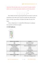
(Special note: When the address needs to be set beyond 63, the address should be dialed to set it to 0, and the station address should be set in IO Config software) Reset: Module reset button, long pressing the button for more than 5 seconds and all parameters of the module will be restored to the default value. When the Reset button is activated, a green indicator will light up in the upper left corner of the button. Config: configured ports, it is standard MicroUSB interface for configuring device parameters and firmware upgrades. PWR Power State (GREEN) ON OFF STAT Module State (RED/GREEN)...
Open the catalog to page 24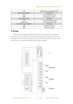
Modbus data exchanging failure Definition IO initialization normal IO initialization failure Definition IO communication normal IO communication failure Definition Field Power Normal Field Power Failure IER IO Error (RED) OFF Double Flash Field Power State (GREEN) 4 Wiring Please note when wiring: for the internal construction, two terminals of SV+ have been short-connected, two terminals of SV- have been short-connected, two terminals of FV+ have been short-connected, and two terminals of FV- have been short-connected. For external it only needs to access one system power supply and one field...
Open the catalog to page 25
http:// www.odotautomation.com
Open the catalog to page 26All ODOT Automation catalogs and technical brochures
 C3351
C33518 Pages
 ODOT C series remote IO
4 Pages
 BOXIO 64
4 Pages
 ODOT remote IO catalogue
20 Pages
 PLC
PLC59 Pages
 New small ODOT brochure
16 Pages
 CN-8034
2 Pages
 CN-8033
2 Pages
 CN-8032
2 Pages
 CN-8012
2 Pages
 CN-8011
2 Pages
 CN-8031
2 Pages
 ODOT-MS100T Serial User Manual
15 Pages
 Remote I/O module
36 Pages
 CT-7221
17 Pages
 CT5800
15 Pages
 CT4234
20 Pages
 CT3804
21 Pages
 CT-3713
19 Pages
 CT3238
19 Pages
 CT-3158
19 Pages
 CT2718
18 Pages
 CT2228
18 Pages
 CT623F
23 Pages
 CT-222F
19 Pages
 CT-121F
21 Pages
 ODOT-PNM02 User Manual_V1.5.
37 Pages
 MG-IOT03 User Manual_V1
24 Pages
 ODOT-IOT02
44 Pages
 ODOT AIOBOX - Integrated IO module
149 Pages
 ODOT-S7PPIV2.0
31 Pages
 ODOT-PNM02
31 Pages
 ODOT-S4E2
56 Pages
 ODOT-IOT01
79 Pages


Archived catalogs
 ODOT-S1E1 User Manual 20200720
30 Pages
- Ethernet switch
- Industrial network switch
- ODOT digital I/O
- ODOT analog I/O
- DIN rail mounted network switch
- RJ45 network switch
- ODOT digital I/O module
- Communication gateway
- Unmanaged switch
- Industrial gateway
- Fieldbus gateway
- Programmable logic controller
- ODOT Fieldbus I/O module
- ODOT analog I/O module
- ODOT serial I/O
- ODOT remote I/O
- Fast network switch
- ODOT DIN rail converter
- 8 ports network switch