
- Catalogs
- ODOT Automation
- MG-CANEX User Manual 20200803_V1.2


MG-CANEX User Manual 20200803_V1.2

MG-CANEX User Manual 20200803_V1.2
- Product Functions: The MG-CANEX is a protocol converter that translates CANopen to Modbus TCP, acting as a master in the CANopen network. It supports PDO, SDO, and error control with Heartbeat, and allows synchronous and asynchronous message sending. It can be accessed by up to 5 TCP clients simultaneously.
- Functional Characteristics: Includes configuration software for parameter setup, supports up to 5 TCP clients, has a double Ethernet port with switch function, and provides 2KV network port isolation protection. It supports various Modbus TCP function codes and has a 6KB data buffer.
- Technical Parameters: Operates within a temperature range of -40 to 85℃, with a power consumption of max. 110mA@24V. Supports a CAN baud rate of 10K~1Mbps and can connect up to 16 CANopen slave stations.
- Product Appearance: Includes 6 LED status indicators for power, system fault, Ethernet operation, and CAN operation status.
- Terminal Definition: Uses 10Pin 3.81mm distance unplug wiring terminals for CAN interface and power connections.
- System Reset: A reset button is available to restore factory settings if the IP address or port number is forgotten.
- Operating Principle: Uses address mapping to convert CANopen network data to Modbus TCP data store. TPDO and RPDO are mapped to Modbus discrete input and register areas, respectively.
- Network Function: Can scan up to 127 nodes on the CANopen network, with itself occupying one node address. Emergency messages are sent with the highest priority in case of fatal errors.
- Overview: Provides an introduction to the CANopen protocol, including network management and data object transfer protocols.
- Error Handling: Outlines various error codes and their meanings, such as CAN overrun, Error Passive, and Heartbeat Error. Describes the use of an 8-bit error register to map internal errors and trigger emergency messages for critical errors.
- Network Management: CANopen NMT network management is achieved by reading and writing to the NMT control domain. Specifies command values for starting, stopping, and resetting nodes, and explains the states of network nodes.
- SDO Service Data Objects: Details the process for reading and writing SDOs, including setting object indices, triggering SDO transmissions, and handling errors.
- IOConfig Software: Instructions for installing and using the IOConfig software are provided. Allows for the configuration of gateway parameters, monitoring of channel data, and modification of module parameters.
- Software Installation: Describes the installation process for IOConfig software, including loading hardware support packages and configuring the software interface.
- Gateway Configuration: Steps for creating new projects, searching for gateways, and configuring gateway parameters are outlined. Explains how to export address tables and configuration information.
- Network Card Setup: Set the local network card to 192.168.1. Use the shortcut key to select the local network card and click 'Search for Devices' to scan for gateways on the network.
- Gateway Parameters: View basic information, process data, configuration parameters, and address table parameters. Key parameters include module name, hardware version, software version, and communication parameters.
- Equipment Parameters: Port mirroring options, Modbus TCP parameters, and CANopen parameters.
- Modifying Gateway IP Address: Change the IP address and gateway parameters in the Modbus TCP settings.
- CANopen Slave Parameters: Manage CANopen slave stations by adding, renaming, and configuring them.
- Service Data Object (SDO) Management: Configure SDO read and write commands.
- PDO Configuration: Set up TPDO and RPDO data inputs and outputs.
- Configuration Download and Upload: Download the configuration to the gateway and upload configuration to assign PDO numbers and COB-ID numbers.
- Firmware Update: Use IO Config software for firmware updates.
- Product Application Example: Demonstrates communication between a remote IO with CANopen protocol and an upper computer with Modbus TCP protocol.
- Specifications: CANopen is built on the Control Area Network (CAN) and includes communication and device sub-protocols. Commonly used in servo systems for its high real-time capabilities.
- Network Management (NMT): Operates in a master-slave mode, where one NMT master controls multiple NMT slaves.
- Service Data Object (SDO): Follows a client-server model, allowing access to a device's object dictionary.
- Error Codes: Lists various error codes and their descriptions.
- Process Data Object (PDO): Used for real-time data transmission in a producer-consumer pattern.
- Appendix: Provides an introduction to the CANopen protocol, detailing its structure and functionality within industrial control systems.
Catalog excerpts

od*t Sichuan Odot Automation System Co., Ltd
Open the catalog to page 1
od*t Sichuan Odot Automation System Co., Ltd CANopen to Modbus TCP protocol converter ODOT Automation System Co., Ltd. 2015-5 Copyright ©2019 ODOT Automation all rights reserved
Open the catalog to page 2
od*t Sichuan Odot Automation System Co., Ltd Version information The following changes have been made to the document: Ownership rights information Without the permission of the copyright owner, all or part of this document shall not be republished as a paper or electronic document. Disclaimer This document is only intended to assist the reader in using the products, and the company shall not be responsible for any loss or error caused by the use of the information in this document. The product and text described in this document are under constant development and refinement. ODOT Automation...
Open the catalog to page 3
od*t Sichuan Odot Automation System Co., Ltd Software download Please log on the official website: www.odotautomation.com and click on the corresponding product page to download.
Open the catalog to page 4
http:// www.odotautomation.com
Open the catalog to page 5
1. Product Overview 1.1 Product Functions MG-CANEX is a protocol converter from CANopen to Modbus TCP. The device plays as the master in the CANopen network and it could be connected to the standard CANopen slave devices. The data transmission http:// www.odotautomation.com
Open the catalog to page 6
OCM Sichuan Odot Automation System Co., Ltd supports PDO, SDO, and error control supports Heartbeat. It Supports synchronous and asynchronous message sending. As a TCP server in Modbus TCP network, the device could be accessed by 5 TCP clients at the same time, and it could be connected to PLC controller and various kinds of configuration software. It could also connect optical transceiver and to realize long-distance data transmission. 1.2 Functional characteristics ♦ The gateway comes with its own configuration software, and the parameter configuration information is downloaded to the gateway...
Open the catalog to page 7
od*t Sichuan Odot Automation System Co., Ltd x05, 0 x06, 0 x0F, 0 x10. ♦ 6KB large data buffer, more data transfer volume. ♦ CAN interface supports CANopen working mode. ♦ CAN interface Baud rate: 10K~1Mbps. ♦ CANopen protocol conforms to DS301 V4.02 and supports NMT master, PDO, SDO and Heartbeat. ♦ It supports one-key reset function to restore factory Settings. ♦ 35mm DIN-rail installation. ♦ EMC meets EN 55022:2010 & EN55024:2010 international standards. 1.3 Technical parameters The technical parameters of this product are shown in Table 1. Please use this product within the parameters of...
Open the catalog to page 8
od*t Sichuan Odot Automation System Co., Ltd Tablel. Technical parameters
Open the catalog to page 9
od*t Sichuan Odot Automation System Co., Ltd 2.2 Indicator light description The equipment has 6 LED status indicator lights, whose symbol definition and status description are shown in "Table 2". Table 2. Indicator light instructions
Open the catalog to page 10
od*t Sichuan Odot Automation System Co., Ltd
Open the catalog to page 11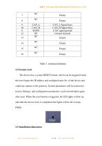
od*t Sichuan Odot Automation System Co., Ltd Table 3. terminal definition 2.4 System reset The device has a system RESET button, which can be triggered when the user forgets the IP address and configured port No. of the device and could not connect to the gateway. System parameters will be restored to factory Settings, and configuration parameters can be downloaded again after reset. When the reset button is triggered, all LED lights will be on, and after the device reset is completed, the lights will be off (except PWR).
Open the catalog to page 12
CANopen to Maftj MG-CANEX S-COV 9-3$ VO led an* FYri? PowtflOtA STA run >A5<*o’CPCAf , ERR UoObwfrTC^CAVope"*
Open the catalog to page 13
4. Product usage 4.1 Operating principle of gateway Gateway protocol transformation belongs to address mapping mode, and the data of all devices in CANopen network are mapped to Modbus TCP data store. The TPDO of the CANopen slave equipment is mapped to the Modbus discrete quantity input and input register areas, and the RPDO is mapped to the Modbus coil and hold register areas. The SDO read command of the CANopen station device is mapped to the Modbus input register area (3XXXX), and the SDO write command is http:// www.odotautomation.com
Open the catalog to page 14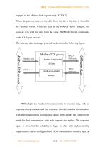
mapped to the Modbus hold register area (4XXXX). When the gateway receives the data from the slave, the data is stored in the Modbus buffer. When the data in the Modbus buffer changes, the gateway will send the data from the slave RPDO/SDO write commands to the CANopen network. The gateway data exchange principle is shown in the following figure. Modbus write Modbus Output buffer 3K Byte Modbus read Modbus Input buffer PDO adopts the producer/consumer mode to transmit data, with no response except request, and fast response, which is suitable for situations with high requirements on response...
Open the catalog to page 15
od-t Sichuan Odot Automation System Co., Ltd PDO can be configured to transfer data. 4.2 Data objects are mapped in the Modbus cache 4.3 Network function 4.3.1 Network scanning The largest number of 127 nodes on the CANopen network, the gateway itself occupies one node address. The basic condition of the slave equipment on the CANopen network can be preliminarily scanned through the network scanning function.
Open the catalog to page 16
od«t Sichuan Odot Automation System Co., Ltd Network scan function is realized by adding network scan module. The corresponding relation of the data address of the network scanning module is as follows: Note: Green: read only; Blue: Feedback Control process: 1. Output trigger bit 0->1 rising edge, start the scan. 2. The scanning state is set to 1, and the number of nodes and module information are all reset. 3. Wait for the scan to complete, and the status bit in the scan is cleared to zero. 4. The number of nodes stores all nodes scanned by the current network, and the node ID and node state...
Open the catalog to page 17
OCM Sichuan Odot Automation System Co., Ltd the device and is sent to other devices with the highest priority by the relevant application device. Suitable for interrupt type error warning signals. An emergency message consists of 8 bytes in the following format: sender ^receiver(s)
Open the catalog to page 18All ODOT Automation catalogs and technical brochures
 C3351
C33518 Pages
 ODOT C series remote IO
4 Pages
 BOXIO 64
4 Pages
 ODOT remote IO catalogue
20 Pages
 PLC
PLC59 Pages
 New small ODOT brochure
16 Pages
 CN-8034
2 Pages
 CN-8033
2 Pages
 CN-8032
2 Pages
 CN-8012
2 Pages
 CN-8011
2 Pages
 CN-8031
2 Pages
 Remote I/O C Series
376 Pages
 ODOT-MS100T Serial User Manual
15 Pages
 Remote I/O module
36 Pages
 CT-7221
17 Pages
 CT5800
15 Pages
 CT4234
20 Pages
 CT3804
21 Pages
 CT-3713
19 Pages
 CT3238
19 Pages
 CT-3158
19 Pages
 CT2718
18 Pages
 CT2228
18 Pages
 CT623F
23 Pages
 CT-222F
19 Pages
 CT-121F
21 Pages
 ODOT-PNM02 User Manual_V1.5.
37 Pages
 MG-IOT03 User Manual_V1
24 Pages
 ODOT AIOBOX - Integrated IO module
149 Pages
 ODOT-S7PPIV2.0
31 Pages
 ODOT-PNM02
31 Pages
 ODOT-S4E2
56 Pages
 ODOT-IOT01
79 Pages
 ODOT-IOT02
44 Pages


Archived catalogs
 ODOT-S1E1 User Manual 20200720
30 Pages

- ODOT network switch
- ODOT industrial network switch
- ODOT digital I/O
- ODOT I/O module
- Gigabit Ethernet ethernet switch
- ODOT analog I/O
- ODOT RJ45 network switch
- ODOT digital I/O module
- ODOT DIN rail network switch
- Waterproof network switch
- Communication gateway
- ODOT unmanaged switch
- Redundant network switch
- Industrial gateway
- Fieldbus gateway
- ODOT Fieldbus I/O module
- ODOT analog I/O module
- ODOT serial I/O
- ODOT DIN rail converter