
- Catalogs
- ODOT Automation
- CT2228


CT2228

CT2228
The Remote IO system comprises a network adapter module and extended IO modules. The network adapter manages fieldbus communication, linking with host controllers or computers. Extended IO modules connect with field sensors, collecting signals and sending them to the network adapter. The system supports various communication protocols like Modbus, Profibus-DP, Profinet, EtherCAT, and more. It offers flexibility in combining network adapters and IO modules to meet field requirements efficiently.
Module Features
The ODOT-C series features a remote I/O module with an adapter module on the left and extended I/O modules on the right. LED indicators provide status updates for power, operation, and I/O channels. Ground protection is ensured through a metal resilient sheet for effective grounding.
Wiring and Installation
Wiring is facilitated through a push-in method, allowing easy and safe connections. Modules are installed on a 35 mm DIN-Rail with manual locking mechanisms. The adapter size is 115x51.5x75mm, and the I/O module size is 115x14x75mm.
Extended IO Module: CT-2228
This module supports 8-channel digital output with 24VDC, capable of driving field equipment like relays and solenoid valves. It features optocoupler isolation, LED indicators for each channel, and protections against thermal shutdown, overcurrent, short circuit, and overload.
Technical Parameters
General parameters include a power consumption of [email protected], opto-couple isolation, and a nominal field power of 24Vdc. The module operates within -40~85℃ and 5%~95% RH, with an IP20 protection class. Output parameters specify a typical current of 500mA per channel and various protection functions.
Hardware Interface
The module includes indicators for power, module state, and output channels. Terminal definitions specify connections for signal output and power input.
Process Data and Configuration
Output data is defined by bit positions, indicating valid or invalid output signals. Configuration parameters allow setting fault actions and values for output channels, ensuring proper operation during communication issues.
Catalog excerpts

od*t Odot Automation System Co., Ltd http:// www.odotautomation.com
Open the catalog to page 1
Od»t Odot Automation System Co., Ltd Odot Automation System C°., Ltd* 2020-2 Copyright ©2020 Odot Automation all rights reserved http:// www.odotautomation.com
Open the catalog to page 2
Ownership rights information Without the permission of the copyright owner, all or part of this document shall not be republished as a paper or electronic document. Disclaimer This document is only intended to assist the reader in using the products, and the company shall not be responsible for any loss or error caused by the use of the information in this document. The product and text described in this document are under constant development and refinement. Odot Automation System Co., Ltd. has the right to modify this document without notifying users. Software download Please log on the official...
Open the catalog to page 3
od*t Odot Automation System Co., Ltd http:// www.odotautomation.com
Open the catalog to page 4
1 Product Overview Remote IO system consists of network adapter module and extended IO module. The network adapter module controls fieldbus communication and it realizes communication link with host station controller or host computer software. The extended IO module controls the connection with the input and output sensors in the field. At first the Input IO module collects the field signals and sends it to the network adapter through the internal bus. Secondly the controller reads and processing data from the adapter through the field bus, and it writes the output data into the network adapter,...
Open the catalog to page 5
od*t Odot Automation System Co., Ltd High speed backplane bus, the refresh cycle of 32 modules is 1ms. • The channels carry with Complete ODOT status indicator lights. self-design. Multiple input/output modules: DI/DO, AI/AO, special modules, extended power modules. Terminal Module 1.2 Module Layout The ODOT-C series is a remote I/O module. The adapter module lies on the far left, and on the right are extended I/O modules. http:// www.odotautomation.com
Open the catalog to page 6
1.3 LED Indicators The user can easily check the power state of adapter and I/O module, I/O module operating state, and the number of I/O channels though LED state. And the detailed indicator state should refer to the related adapter or IO modules. 1.4 Ground Protection There is one metal resilient sheet on the back of the module, which is used for effective grounding with the guide rail. The metal resilient sheet and the adapter PE (protective earthing) are connected internally.
Open the catalog to page 7
Use push-in method to connect single-wire or crimp terminal wires without any other tools. Users can save wiring time and ensure a safe operation regardless of wiring experience. The module equips with a wiring fixed end for cable harness, which is used to fix the cable when the IO module is wired with multiple cables. 1.6 Installation and Removal DIN-Rail Lock could be safely and reliably installed on 35 mm DIN-Rail. There is a manual closure buckle on the upper side of all modules for locking, and a manual buckle is on the left side of the adapter for locking the guide rail. http:// www.odotautomation.com...
Open the catalog to page 8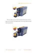
When the module is removed, it needs to manually unlock the guide rail on the upper side of the module. For the adapter module, you also need to unlock the left rail buckle counterclockwise.
Open the catalog to page 9
od*t Odot Automation System Co., Ltd Adapter size: 115*51.5*75mm I/O module size: 115*14*75mm 2 Extended IO module CT-2228: 8 channel digital output/24VDC/ Source type 1 Module features ♦ the module supports 8-channel digital output, output high level effective, and output voltage 24 V ♦ the module could drive field equipment (relay, solenoid valve, etc.) ♦ the module internal bus and field output are isolated by optocoupler ♦ the module carries with 8 digital output channel LED indicator ♦ the module has the functions of thermal shutdown and overcurrent protection ♦ the module supports short...
Open the catalog to page 10
od*t Odot Automation System Co., Ltd http:// www.odotautomation.com
Open the catalog to page 11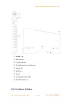
© Module Type © State indicator © Channel indicator © Wiring Terminal and identification © Internal Bus © Field Power © Buckle © Grounding Resilient Sheet @ Fixed Wiring Harness
Open the catalog to page 12
© Power LED indicator (red) © Module State LED indicator (red/green) © Output channel LED indicator (green) DOO DOI When the output signal of the output channel is valid, the corresponding field channel LED indicator is lit. 3.3 Terminal definition
Open the catalog to page 13
Note 1: When the red LED indicator beside the 24V terminals lights up, this is indicating that the module output has passed the field bus, so the 24V terminals could be disconnected. The max.output current of each channel is 500mA, and the max. sum of the current of all the output channels is 4A.When the total current exceeds 2A, and it is suggested to connect the power in the 24V terminal at the same time to avoid the on-site power current exceeding its limit. When the red LED indicator beside the 24V terminal goes off, it means that the module output is not powered. In this case, the power...
Open the catalog to page 14
od*t Odot Automation System Co., Ltd http:// www.odotautomation.com
Open the catalog to page 15
Data description: Fault Action for Output Ch#(0-7): When IO module detects the internal bus communication is abnormal and enters offline mode, and output data will be processed in this mode. (Default: 0) 0: Hold Last Output State 1: Output F ault Value
Open the catalog to page 16
Od*t Odot Automation System Co., Ltd Fault Value for Output Ch#(0-7): When the fault output mode is 1, this bit sets the fault output value, and when the internal bus of IO module is offline, this setting value will be output.(Default: 0) 0: Output low level. 1: Output high level.
Open the catalog to page 17
______________________________________________________________ Odot Automation System Co., Ltd. Add: No.6 Hongsheng Road, Hi-Tech District, Mianyang, Sichuan, China. Tel: +86-0816-2538289 Zip Code: 621000 Email:[email protected] Web: www.odotautomation.com http:// www.odotautomation.com
Open the catalog to page 18All ODOT Automation catalogs and technical brochures
 C3351
C33518 Pages
 ODOT C series remote IO
4 Pages
 BOXIO 64
4 Pages
 ODOT remote IO catalogue
20 Pages
 PLC
PLC59 Pages
 New small ODOT brochure
16 Pages
 CN-8034
2 Pages
 CN-8033
2 Pages
 CN-8032
2 Pages
 CN-8012
2 Pages
 CN-8011
2 Pages
 CN-8031
2 Pages
 Remote I/O C Series
376 Pages
 ODOT-MS100T Serial User Manual
15 Pages
 Remote I/O module
36 Pages
 CT-7221
17 Pages
 CT5800
15 Pages
 CT4234
20 Pages
 CT3804
21 Pages
 CT-3713
19 Pages
 CT3238
19 Pages
 CT-3158
19 Pages
 CT2718
18 Pages
 CT623F
23 Pages
 CT-222F
19 Pages
 CT-121F
21 Pages
 ODOT-PNM02 User Manual_V1.5.
37 Pages
 MG-IOT03 User Manual_V1
24 Pages
 ODOT AIOBOX - Integrated IO module
149 Pages
 ODOT-S7PPIV2.0
31 Pages
 ODOT-PNM02
31 Pages
 ODOT-S4E2
56 Pages
 ODOT-IOT01
79 Pages
 ODOT-IOT02
44 Pages


Archived catalogs
 ODOT-S1E1 User Manual 20200720
30 Pages

- ODOT network switch
- ODOT industrial network switch
- ODOT digital I/O
- Gigabit Ethernet ethernet switch
- ODOT analog I/O
- ODOT RJ45 network switch
- ODOT digital I/O module
- ODOT DIN rail network switch
- Waterproof network switch
- Communication gateway
- ODOT unmanaged switch
- Redundant network switch
- Industrial gateway
- Fieldbus gateway
- ODOT Fieldbus I/O module
- Programmable logic controller
- ODOT analog I/O module
- ODOT serial I/O
- ODOT DIN rail converter