- Catalogs
- ODOT Automation
- B series integrated IO catalogue BOXIO 64
- Company
- Products
- Catalogs
- News & Trends
- Exhibitions
B series integrated IO catalogue BOXIO 64
1 /160Pages

B series integrated IO catalogue BOXIO 64
1 /160Pages
Catalog excerpts

B Series Modular integrated I/O User Manual http:// www.odotautomation.com
Open the catalog to page 1
B Series - Modular integrated I/O Odot Automation System Co., Ltd. 2021-04 Copyright ©2021 Odot Automation all rights reserved http:// www.odotautomation.com
Open the catalog to page 2
Version Information Release version Updated wiring diagram Ownership rights information Without the permission of the copyright owner,all or part of this document shall not be republished as a paper or electronic document. Disclaimer This document is only intended to assist the reader in using the products, and the company shall not be responsible for any loss or error caused by the use of the information in this document. The product and text described in this document are under constant development and refinement. Odot Automation System Co., Ltd. has the right to modify this document without...
Open the catalog to page 3
http:// www.odotautomation.com
Open the catalog to page 4
http:// www.odotautomation.com
Open the catalog to page 9
1 Product Overview ODOT B series integrated I/O module consists of communication board (COMM board) module and extended IO module. The COMM board module is responsible for the fieldbus communication and realizes the communication connection with the master controller or the upper computer software. The extended IO module is responsible for connecting the input and output sensors on the site. The input IO module collects various signals on the site and sends them to the COMM board through the internal bus. And the controller reads and processes data from the COMM board through the field bus, and...
Open the catalog to page 10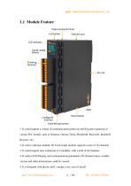
1. It could support a variety of communication protocols and IO point expansion of various PLC brands, such as Siemens, Omron, Delta, Mitsubishi, Rockwell, Beckhoff, Keyence, etc. 2. It carries optional modular IO. Each single module supports a max of 16 channels. 3. It could support max expansion of 4 modules, with a total of 64 channels. 4. It carries LCD Display and communication parameters, IO channel status, module version and other information could be viewed. 5. It is designed with plastic shell, compact size, easy to install. http:// www.odotautomation.com
Open the catalog to page 11
1.2 Module Structure ODOT B series is integrated I/O module with modular combinations inside. The power supply and COMM board are at the bottom, and the IO module communicates with the COMM board through the backplane (the green module as below). It could support expansion max of 4 IO slots (only 2 IO slots are installed in below diagram). http:// www.odotautomation.com
Open the catalog to page 12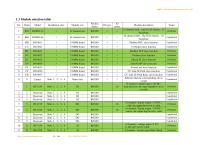
1.3 Module selection table No. Installation slots Module sort Product Series COMM board COMM board CANopen slave function COMM board Modbus-TCP slave function COMM board Profinet slave function COMM board EtherCAT slave function COMM board EtherNet/IP slave function COMM board PowerLink slave function COMM board COMM board BOXIO BOXIO Name only CC-Link IE Field slave function CC-Link IE Field Basic slave function Indicates that the corresponding slot is vacant 16 channel / digital input / 24VDC / dual direction, the input high&low level is valid Reserved Reserved Reserved Slots 1,2,3,4 Slots...
Open the catalog to page 13
15bit, single ended 4 channels / current input / 0&4-20mA,± 20mA, 15 bit, Single-ended bipolar 4 channels / RTD input / PT100 / 15bit 4 channels / RTD input / PT1000 / 15bit 4 channels Thermocouple / TC / Input, 24bit BOXIO BOXIO Slots 1,2,3,4 Slots 1,2,3,4 Slots 1,2,3,4 Slots 1,2,3,4 BOXIO BOXIO BOXIO BOXIO Special module Slots 1,2,3,4 Slots 1,2,3,4 Slots 1,2,3,4 Slots 1,2,3,4 Special module Special module Special module Special module BOXIO BOXIO BOXIO BOXIO Slots 1,2,3,4 Slots 1,2,3,4 Slots 1,2,3,4 Slots 1,2,3,4 Slots 1,2,3,4 Slots 1,2,3,4 Slots 1,2,3,4 http:// www.odotautomation.com Published...
Open the catalog to page 14
For example, the I/O module type B32-MT16 consists of the following sub-modules: COMM Board The I/O module type B64-PN1166 consists of the following sub-modules: COMM Board Note: Details please see the selection table above. http:// www.odotautomation.com
Open the catalog to page 15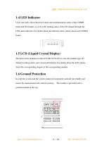
1.4 LED Indicator Users can easily check the power status and communication status of the COMM board and I/O module, as well as the running status of the I/O channel through the LED status indicator. For details about the indicator status, please check each COMM board. 1.5 LCD (Liquid Crystal Display) The front of the module provides 8*8 OR 16*8 LCD to view the module type, IO channel working status, and version information. For details about the LCD, please check the corresponding chapter of the corresponding module. 1.6 Ground Protection In order the system and the system connected instrument...
Open the catalog to page 16
1.7 Wiring Using push-in connection to connect single wire or crimp terminal (ferrule) wire, no need any other tools. It could save wiring time for users regardless of wiring experience, and ensure safe connection. The IO carries wiring harness at the bottom of the module. It could fix cables when the I/O module is connected to multiple cables. http:// www.odotautomation.com
Open the catalog to page 17
1.8 DIN-Rail installation DIN-Rail Lock could be safely and reliably installed on 35 mm DIN-Rail. http:// www.odotautomation.com
Open the catalog to page 18
1.9 Installation Size B32 module installation size:110*84*28mm, plused IO wiring terminal size:110*100*28mm http:// www.odotautomation.com
Open the catalog to page 19
2 Communication Board (COMM Board) BN-8031:Modbus-TCP COMM Board 1 The COMM Board Overview BN-8031 Modbus-TCP COMM board supports standard Modbus-TCP server communication, and the Ethernet supports the cascading function of dual network port switches. The device supports the simultaneous access of 5 clients. It supports 01/02/03/04/05/06/15/16 function code and Modbus application of watchdog. The sum of process data input and output is up to 8192 bytes and it supports 4 extended I/O modules. The module carries diagnostic function and it could monitor the communication status of the I/O module...
Open the catalog to page 20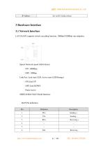
3 Hardware Interface 3.1 Network Interface LAN1/LAN2 supports switch cascading function, 10Mbps/100Mbps rate adaption. Speed: Network speed LED (Green) ON: 100Mbps OFF: 10Mbps Link/Act: Link state LED, Active state LED(Orange) ON:Link UP OFF:Link DOWN Flash:Active SHIELD:RJ45 RJ45 Shield Interface http:// www.odotautomation.com
Open the catalog to page 21All ODOT Automation catalogs and technical brochures
 C3351
C33518 Pages
 ODOT C series remote IO
4 Pages
 BOXIO 64
4 Pages
 ODOT remote IO catalogue
20 Pages
 PLC
PLC59 Pages
 New small ODOT brochure
16 Pages
 CN-8034
2 Pages
 CN-8033
2 Pages
 CN-8032
2 Pages
 CN-8012
2 Pages
 CN-8011
2 Pages
 CN-8031
2 Pages
 Remote I/O C Series
376 Pages
 ODOT-MS100T Serial User Manual
15 Pages
 Remote I/O module
36 Pages
 CT-7221
17 Pages
 CT5800
15 Pages
 CT4234
20 Pages
 CT3804
21 Pages
 CT-3713
19 Pages
 CT3238
19 Pages
 CT-3158
19 Pages
 CT2718
18 Pages
 CT2228
18 Pages
 CT623F
23 Pages
 CT-222F
19 Pages
 CT-121F
21 Pages
 ODOT-PNM02 User Manual_V1.5.
37 Pages
 MG-IOT03 User Manual_V1
24 Pages
 ODOT-IOT02
44 Pages
 ODOT AIOBOX - Integrated IO module
149 Pages
 ODOT-S7PPIV2.0
31 Pages
 ODOT-PNM02
31 Pages
 ODOT-S4E2
56 Pages
 ODOT-IOT01
79 Pages


Archived catalogs
 ODOT-S1E1 User Manual 20200720
30 Pages
- Ethernet switch
- Industrial network switch
- ODOT digital I/O
- DIN rail mounted network switch
- ODOT analog I/O
- RJ45 network switch
- ODOT digital I/O module
- Communication gateway
- Unmanaged switch
- Industrial gateway
- Fieldbus gateway
- ODOT Fieldbus I/O module
- ODOT analog I/O module
- ODOT serial I/O
- ODOT DIN rail converter
- ODOT remote I/O
- Ethernet converter
- Fast network switch