- Catalogs
- Odinvision
- Digital Light Source Controller
- Company
- Products
- Catalogs
- News & Trends
- Exhibitions
Digital Light Source Controller
1 /16Pages
Digital Light Source Controller
1 /16Pages
Catalog excerpts
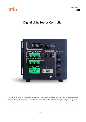
User Manual Digital Light Source Controller The HDT24 series digital light source controller is a high-power, multi-functional controller featuring four output channels. It supports both strobe and continuous illumination modes and offers multiple configuration options for ease of use.
Open the catalog to page 1
User Manual I. Features A. High Current Output: Each channel supports a load current of up to 3A. B. Brightness Control: Adjustable via a rotary knob or serial communication interface. C. Brightness Levels: Provides 256 brightness levels, ranging from 0 to 255. D. Opto-isolated External Trigger: Ensures precise triggering. E. Safety Features: Includes power-off memory, overload, and short-circuit protection.
Open the catalog to page 2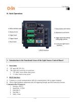
User Manual III. Basic Operations > Introduction to the Functional Areas of the Light Source Control Board1. Power Input: A. DC input (DC24V 4A). B. The right-side switch has two positions: 1. “O” (Off): Turns off the main power. A. Connects to a serial communication cable for communication with an upper computer. B. Allows light brightness adjustment and soft triggering through specified instruction formats. Communication Parameters:
Open the catalog to page 3
User Manual 6. Control Format: ASCII commands 7. Multiple channels separated by commas , Refer to the communication protocol for details. 3. Trigger Output: Four input ports labeled TG1, TG2, TG3, and TG4 in sequence. For each input, connect the positive signal to the "+" terminal and the negative to the "-" terminal. Upon receiving a rising edge signal (DIP switch 9 set to the upper position), the controller drives the corresponding light source and outputs a pulse signal to the Camera Trigger Input port. Trigger Input: Outputs corresponding pulse signals based on received input signals. Output...
Open the catalog to page 4
9. Trigger Input Pulse Rising/Falling Edge Selector: Switches between rising and falling edge trigger modes for input pulses. Four output ports labeled CH1, CH2, CH3, and CH4 in sequence, corresponding to their respective trigger inputs and outputs. When the controller detects a valid trigger signal (rising or falling edge), it continuously drives the light source. The light source remains illuminated until a reverse-level trigger signal is detected. Upon receiving a single valid trigger signal (rising edge), the controller drives the light source for the corresponding channel. Simultaneously,...
Open the catalog to page 5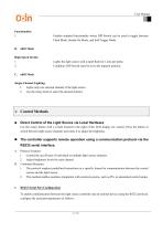
User Manual Enables standard functionality where DIP Switch can be used to toggle between Flash Mode, Steady-On Mode, and Soft Trigger Mode. Lights the light source with a rapid flash for 1.2ms per pulse. Condition: DIP Switch must be set to the topmost position. 1. Lights only one selected channel of the light source. 2. Use the rotary knob to select the desired channel. Use the rotary button with a switch located to the right of the LED display for control. Press the button to switch between light source channels and rotate it to adjust the brightness. 1. Control the on/off state of individual...
Open the catalog to page 6
User Manual A. Port: Replace COM* with the specific port number assigned to the controller during setup. B. Baud Rate: Ensures the speed of communication matches between devices. C. Data Bits & Stop Bits: Define the format of the transmitted data. D. Parity Bit: No error-checking parity is used. E. Control Character: ASCII-encoded commands are used to communicate. F. Termination: Each command should end with a Carriage Return (\r) to signal the end of a command. light source controller receives control commands through the serial port in the following format: Command Structure 1. Channel On/Off...
Open the catalog to page 7
c. \r: End of the command (carriage return). 2. Turn off Channel 2 and set its brightness to 50 Command: M20=0,I20=50\r b. I20=50: Set the brightness of Channel 2 to 50 (the brightness value is ignored when the channel is off). 3. Control multiple channels simultaneously e. Use a comma , to separate multiple commands, and end the sequence with \r. A. Channel Numbers and Format 1. Channel numbers must be clearly indicated with the prefix M (for switching) or I (for brightness), e.g., M10 and I10 for Channel 1. 2. Ensure commands are written in the correct format without extra spaces or invalid...
Open the catalog to page 8
User Manual • The brightness value range is from 0 to 255 (where 0 is the lowest brightness, and 255 is 1. Before sending commands, ensure the "LOCK/UNLOCK" switch is toggled to the UNLOCK state. 2. When in the LOCK state, commands sent via RS232 are ignored. Use the specified channel numbers and formats (M10, I10, etc.) in your commands. You can control multiple channels simultaneously by separating commands with commas ,. Ensure proper syntax and format. A. Turn ON Channel 2 and set its brightness to 200: B. Turn OFF Channel 3 and set its brightness to 50: C. Simultaneously control multiple...
Open the catalog to page 9
User Manual 2. Verify Serial Port Settings: Ensure the correct baud rate and port number are configured in the serial communication tool. 1. Check Power Supply: Ensure the light source controller is powered on. 2. Verify Command Format: Ensure the command format is correct and includes the necessary terminator (carriage return, \r). 1. Check Brightness Range: Ensure the brightness value in the command is within the 0-255 range. 2. Unlock the Controller: Ensure the light source controller is in the UNLOCK state to allow control. The controller will not accept commands if it is locked. This communication...
Open the catalog to page 10
User Manual 110=100: This command is used to set the brightness level of channel 1. 1. I10: Refers to the command for controlling the brightness of channel 1. 2. =100: Sets the brightness of channel 1 to 100, where the brightness value can range from 0 to 255. a. 0: Minimum brightness (OFF or no light). b. 255: Maximum brightness (full intensity). 1. 110=100: Sets the brightness of channel 1 to 100. 2. 110=255: Sets the brightness of channel 1 to the maximum (255). The baud rate is 115200, which means the data is transmitted at a rate of 115200 bits per second (bps). This is the speed at which...
Open the catalog to page 11All Odinvision catalogs and technical brochures
 Machine Vision Lens
19 Pages
 AVB & SDK Software manual
20 Pages
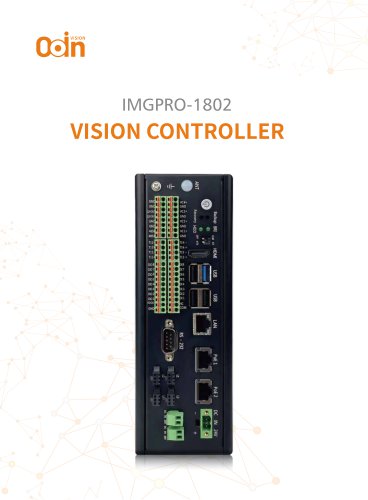 Vision Controller
5 Pages
 MACHINE VISION CAMERAS
6 Pages
 CABLES
16 Pages

- Connector
- Electrical cable
- Data connector
- Visible imager
- CMOS camera module
- Industrial camera module
- Automation software solution
- Copper cable
- Copper electrical cable
- Analysis software solution
- Power cable
- Monitoring camera system
- Windows software
- Real-time software
- Industrial connector
- USB camera module
- Multi-strand cable
- Detection camera system
- IP67 connector
- Multi-wire electrical cable