
- Catalogs
- OBO Bettermann
- Cable tray systems

Cable tray systems

Cable tray systems
Catalog excerpts

► Cable trays of every size and design ► Optimum cable routing in all areas of electrical installation ► Complete product ranges with all logical system components for any task ► Both for horizontal and vertical cable routing ► Special surfaces for guaranteed corrosion protection - even in external areas
Open the catalog to page 1
Cable tray systems Type overview and components, RKS-M System overview, RKS-M Type overview and components Cable tray system 35 Cable tray system 60 Cable tray system 85 Cable tray system 110 Cable tray system, walkable
Open the catalog to page 2
With its innovative connection, the new RKS-Magic® combines speed, load capacities and safety. Just con- nect the pieces, lock them in place - and you're done. That saves time - and you can increase your installation speed by 100% without the need for screws, connectors Increased installation performance Installation speed with RKS-Magic®
Open the catalog to page 3
Simple working The spring element is permanently connected to the tray and cannot Pe A screwdriver is all that is required - push it under the clip and you're Full compatibility Stock length The RKS-Magic® stock length is the connection means that it has a
Open the catalog to page 4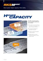
More speed. Higher capacity. More safety. tees an increased capacity and more stability. ► The cable trays do not abut, but area of the sleeve connection ► Load capacity VDE-tested to ► Patented connection guarantees increased capacity ► Stability thanks to innovative connection technology - even at maximum loads
Open the catalog to page 5
Mechanical safety ► Even at maximum load, there is a clean transition at the ► Secure connection in case of Electrical safety ► Equipotential bonding guaranteed permanently without additional
Open the catalog to page 6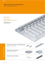
Type overview and components RKS-Magic® Side height: 35 mm Cable tray widths: 100, 200, 300 mm Galvanisation type: Components for all systems Connection and separation, side height-dependent Fittings, side height-dependent Accessories for all side heights
Open the catalog to page 7
System overview
Open the catalog to page 9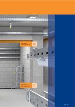
RKS-Magic ® Side height 35 mm RKS-Magic ® Side height 60 mm
Open the catalog to page 10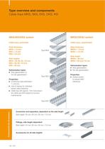
Type overview and components MKS/SKS/EKS system Cable trays, perforated Plate thickness: Side heights: Galvanisation types: hot-dip galvanisation Continuous side perforation barrier strips fastening Cable tray with approx. 15% hole propor- tion (SKS and EKS tested for function MKSU/SKSU system Cable trays, unperforated Plate thickness: Side height: Galvanisation types: Connection and separation, dependent on the side height Fittings, side height-dependent Accessories for all side heights
Open the catalog to page 11
DKS/IKS system Type MKSU Type SKSU Permeable cable trays with 30% hole proportion Plate thickness: Side height: Galvanisation types: ► 30% hole proportion (according to Vds guidelines for use under sprinkler ► IKS cable tray additionally with side perforation for cable penetration ► From width 200 mm with large bottom perforation for cable penetration
Open the catalog to page 12
System overview MKS/SKS/EKS Cable tray system Side height 35, 60, 85, 110 mm
Open the catalog to page 13
Cable tray system walkable
Open the catalog to page 14
OBQ Cable tray systems Cable tray systems RKS-Magic® Cable tray system RKS-Magic® 35 Cable trays Type RKS-Magic Fittings: According to side heights Connecting parts According to side heights The new RKS-Magic® cable tray system permits even faster straight connectors of the cable tray. The innovative, screwless straight connector can be mounted in the blink of an eye. Just connect the ends of the cable tray, lock them in place - and you're done! The long-lasting, static straight connectors can be permanently stabilised by bending the connection flaps. The new RKS-Magic® cable tray is available...
Open the catalog to page 15
Cable tray systems Cable tray systems RKS-Magic® Straight connection, cable tray interconnection Straight connection, cable tray interconnection Straight connection, cable tray interconnection The simple straight connection is created by simple connection of the cable trays. Please observe the mounting direction. The ongoing cable tray is inserted from above from the existing sleeve opening. The optimum straight connection is confirmed by an audible click. Then, use a screwdriver, to turn over the connection lugs in the bottom - and you're done. Straight connection, cable tray interconnection...
Open the catalog to page 16
Cable tray systems Cable tray systems RKS-Magic® Barrier strip fastening with screw connection Screwed barrier strip fastening of the barrier strip , TSG 60, with truss-head screws M6x12. The barrier strip can simply be run over the joint. Vertical adjustable connection of cable trays Vertical adjustable connection of cable tray for construction-side height jumps of any angle. Installation of bend (width 100 - 300 mm) Floor fastening Horizontal angle connection of cable trays Floor fastening at a distance with stand off bracket, type DBL. Width change and end closure Horizontal angle connection...
Open the catalog to page 17
Cable tray systems Cable tray systems RKS-Magic® Installation of vertical add-on tee (top view) Installation of tee (width 100 - 300 mm) Vertical mounting of the add-on tee as lengthwise funnel. Perforation in the cable tray is created on site. For widths > 400 mm, please order connectors separately. With uncut lengths, remove the spring elements on the cable tray, push the tee into the tray on one side (on two sides on outgoing side) and, on the other side, over the connector and fasten it with trusshead screws, type FRSB 6 x 12 mm. With cut lengths, always place the sleeveless side on the fitting....
Open the catalog to page 18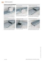
OBQ Cable tray systems Fastening of the mounting plate, type MP, on the side rail of the cable tray. The mounting plate can be fastened to the rail with quick connectors, and permanently fastened using truss-head screws of Screwless cover fastening with cover clamp The MP UNI mounting plate is fastened on the side rail of the cable tray using a truss-head screw. Installation of cover for fitting Cover with turn-buckles are fastened by turning the turn-buckle through 90°. Clamp fastening takes place under the rolled side rail of the cable tray. Edge protection strip for plate ends Screwless cover...
Open the catalog to page 19
Splash pages 04_KTS_Katalog_2008 / en / 29/10/2008 (LLExport_00004) Splash page_Level 3 128 KTS Always indicate the item number when ordering.
Open the catalog to page 21All OBO Bettermann catalogs and technical brochures
 MCF-NAR
4 Pages
 Product innovations 2014
136 Pages
 UFS - Underfloor systems
494 Pages
 EGS Device systems
235 Pages
 LFS Cable routing systems
476 Pages
 BSS. Fire protection systems
338 Pages
 KTS. Cable support systems
500 Pages
 AIK - Onfloor trunking systems
14 Pages
 Mesh cable tray systems
26 Pages
 Earthing systems
22 Pages


Archived catalogs
 Flush mount devices
12 Pages
 OBO rail and Flex duct
13 Pages
- Surge protector
- Profile
- Terminal box
- DIN rail lightning arrester
- Conduit gland
- Class II surge protector
- Wall-mounted splice box
- Waterproof cable gland
- Polymer junction box
- Low-voltage lightning arrester
- IP68 cable gland
- Plastic cable gland
- Plug-in lightning arrester
- Type 1 surge protector
- Waterproof terminal box
- Insulation testing system
- Compact surge suppressor
- Fire-resistant junction box
- Type 3 surge arrester
- PA cable gland