


Side Lock Holders

Side Lock Holders
Technical Specifications and Dimensions
The document provides detailed dimensional data and specifications for various types of tool holders or components, identified by part numbers and types (Type 1, Type 2, Type 3, Type 4). Key dimensions include diameters (D, d, D1, dH6), lengths (L, L1), heights (H, H1), and other parameters such as G and I. These dimensions are given in millimeters and inches, with tolerances specified (notably H6 I.D. tolerance).
Part Numbering and Ordering Examples
Part numbers follow a structured format incorporating size and type information, e.g., CAT40-SLH-0500-105 or HSK63A-SL2-12-95. Ordering examples illustrate how to specify parts based on size, type, and features.
Features and Treatments
- Special anti-rust surface treatment is applied to all components.
- H6 internal diameter (I.D.) tolerance ensures precision fit.
- Some types include built-in coolant tubes for enhanced cooling performance.
Types and Compatibility
The document covers multiple tool holder standards and sizes, including CAT40, CAT50, BT30, BT40, BT50, and HSK63A. Each standard has specific dimensional sets and part numbers. Types 1 and 2 are common across several standards, with Types 3 and 4 appearing in HSK63A components, often featuring coolant tubes.
Thread and Fastening Details
Thread sizes and lengths for fastening screws are specified, such as 1/4-28×1/4, 5/16-24×1/4, 3/8-24×5/16, up to 1-12×7/8. These correspond to the part sizes and types, ensuring proper assembly and secure fastening.
Dimensional Tables Summary
Tables list dimensions for each part number and type, including:
- Diameter dimensions (D, d, D1, dH6)
- Length dimensions (L, L1)
- Height dimensions (H, H1)
- Other parameters (G, I)
- Tolerance and angle specifications (e.g., -65°, -105°, -135°)
These tables enable precise selection of components based on required size and application.
Critical Information and Best Practices
- Ensure selection of correct part number matching the tool holder standard and size.
- Verify H6 I.D. tolerance compliance for precision fit.
- Utilize special anti-rust surface treatment to enhance durability and corrosion resistance.
- Consider coolant tube built-in types for applications requiring enhanced cooling.
- Follow specified thread sizes and lengths for secure fastening.
This structured data supports accurate ordering, assembly, and application of tool holders or related components in machining or tooling environments.
All NT Tool catalogs and technical brochures
 Power Hydro Chuck
13 Pages
 Collet Type Floating Holder
2 Pages
 BCL - BT Clamper
1 Page
 UTS series
36 Pages
 HSK-T series
8 Pages
 HSK serires
85 Pages
 AHO series
42 Pages
 CAT series
55 Pages
 BT series
142 Pages
 HSK Clamper
1 Page
 Slim Hydro Chuck PHC·S
8 Pages
 General Catalog
586 Pages
 OTP Optical Tool Presetter
6 Pages
 "R"- ZERO HOLDER
9 Pages
 ZERO MASTER / ZM-1
1 Page
 MORSE TAPER ADAPTERS / MTA
2 Pages
 TAP HOLDERS / TP3B
2 Pages
 EASY PRESET SERIES / STM
11 Pages
 SHRINKFIT HOLDERS / SRE
8 Pages
 ER COLLET CHUCKS / ERC
12 Pages
 HDC COLLET CHUCKS / HDC-A
7 Pages
 GDC COLLET CHUCKS / GDC
4 Pages
 R-ZERO SETTER / SPZ-2
1 Page
 EASY PRESET SERIES / SDM
7 Pages
 Straight Drill Chuck
7 Pages
 HSK Tightening Fixture
2 Pages
 Simple Setter
7 Pages
 Jacobs Taper Arbors
2 Pages
 High Precision Coolant Collets
10 Pages
 Chamfering Cutter Series
4 Pages
 Quick Change Stub Tapper
4 Pages
 Quick Change Stub Holder
5 Pages
 Milling Chuck Collets
13 Pages
 Contactless Tool Presetter
6 Pages
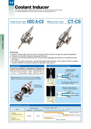 Coolant Inducer
4 Pages
 Hyper Spindle
3 Pages
 Angle Heads
7 Pages
 Keyless Drill Chucks
2 Pages
 Synchronous Tap Holder
11 Pages
 Shrink-Fit Holders
8 Pages
 Heating Device
3 Pages
 R-Zero collet chucks
9 Pages
 New Generation Milling Chucks
15 Pages


- Chuck
- Milling chuck
- Drilling chuck
- Collet chuck
- High-precision chuck
- Collet tool holder
- Milling tool holder
- Drilling tool holder
- BT chuck
- High-precision tool holder
- Morse taper chuck
- Angle gear drives
- Tapping holder
- Quick-change chuck
- ER collet chuck
- Morse taper tool holder
- High-rigidity chuck
- BT tool holder
- High-rigidity tool holder
- Quick-change tool holder