


Shrink-Fit Holders

Shrink-Fit Holders
Technical Specifications and Dimensions
The document provides detailed dimensional data for various tool holders and cutting tools, including parameters such as diameter (D, D1), length (L, L1, L2, l1), and angles (notably 3°). These dimensions are critical for selecting appropriate tooling components compatible with different machine interfaces like CAT40, CAT50, BT40, and HSK40E/HSK63A.
Key Dimensional Parameters
- Diameters range from approximately 2.756 mm to 7.677 mm.
- Lengths (L, L1, L2, l1) vary depending on the part number and tool type, with minimum and maximum clamping lengths specified.
- Angular specifications include consistent 3° taper angles and various angular positions (-105°, -135°, -165°, -195°) related to tool orientation or features.
Part Numbers and Ordering Information
The document lists part numbers such as -SRS0250A, -SRS0312A, -SRS0375A, -SRS0500A, -SRS0625A, and -SRS0750A, which correspond to specific tool sizes and configurations. These are associated with different machine tool interfaces (CAT40, CAT50, BT40, HSK40E, HSK63A).
Ordering examples emphasize the necessity of using two M4 × 5(S) hex-head screws to plug air holes for coolant-through operation, ensuring proper coolant flow and tool performance.
Operational Recommendations and Best Practices
- Always use carbide shank cutters with a tolerance of h6 or better to ensure precision and compatibility.
- For coolant-through operation, air holes must be plugged using specified hex-head screws.
- Coolant tubes may be built-in for certain tool holders, enhancing cooling efficiency during machining.
Additional Features and Notes
- Air holes (M4) are present in the tool holders to facilitate coolant flow; proper sealing is required during operation.
- Minimum and maximum clamping lengths are specified to ensure secure tool holding and optimal machining performance.
- The document includes multiple references to angular positions and taper angles, which are essential for correct tool alignment and mounting.
Summary
This technical document serves as a comprehensive reference for selecting and ordering precision tool holders and cutters compatible with various machine tool interfaces. It details critical dimensions, part numbers, and operational guidelines to ensure proper tool installation, coolant management, and machining accuracy. Adherence to specified tolerances and assembly instructions is emphasized to maintain tool performance and longevity.
Catalog excerpts

L2 L1 L l1 0.39 I (M4) Min. clamping length 2-Air holes Max. clamping length D1 3° d D CAT40-SRS12A-135 Ordering Example Two M4 × 5(S) hex-head screws are necessary to plug the air holes for coolant through operation. Always use a carbide shank cutter with a h6 or better shank tolerance.
Open the catalog to page 2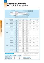
BT40-SRS0500A-135 Ordering Example Two M4 × 5(S) hex-head screws are necessary to plug the air holes for coolant through operation. Always use a carbide shank cutter with a h6 or better shank tolerance. 3° d D I l1 L1 L 0.39 Max. clamping length Min. clamping length 2-Air holes (M4)
Open the catalog to page 3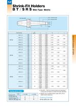
BT40-SRS12A-135 Ordering Example Two M4 × 5(S) hex-head screws are necessary to plug the air holes for coolant through operation. Always use a carbide shank cutter with a h6 or better shank tolerance. 3° d D I l1 L1 L 0.39 Max. clamping length Min. clamping length 2-Air holes (M4)
Open the catalog to page 4
3° d D l1 I 0.39 L1 L Min. clamping length Coolant tube (built-in) Max. clamping length Ordering Example Coolant tube built-in. Always use a carbide shank cutter with a h6 or better shank tolerance.
Open the catalog to page 5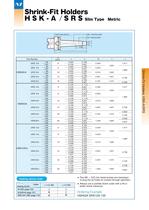
3° d D l1 I 0.39 L1 L Min. clamping length Coolant tube (built-in) Max. clamping length HSK63A-SRS12A-135 Ordering Example Two M4 × 5(S) hex-head screws are necessary to plug the air holes for coolant through operation. Always use a carbide shank cutter with a h6 or better shank tolerance.
Open the catalog to page 6All NT Tool catalogs and technical brochures
 Power Hydro Chuck
13 Pages
 Collet Type Floating Holder
2 Pages
 BCL - BT Clamper
1 Page
 UTS series
36 Pages
 HSK-T series
8 Pages
 HSK serires
85 Pages
 AHO series
42 Pages
 CAT series
55 Pages
 BT series
142 Pages
 HSK Clamper
1 Page
 Slim Hydro Chuck PHC·S
8 Pages
 General Catalog
586 Pages
 OTP Optical Tool Presetter
6 Pages
 "R"- ZERO HOLDER
9 Pages
 ZERO MASTER / ZM-1
1 Page
 MORSE TAPER ADAPTERS / MTA
2 Pages
 TAP HOLDERS / TP3B
2 Pages
 EASY PRESET SERIES / STM
11 Pages
 SHRINKFIT HOLDERS / SRE
8 Pages
 ER COLLET CHUCKS / ERC
12 Pages
 HDC COLLET CHUCKS / HDC-A
7 Pages
 GDC COLLET CHUCKS / GDC
4 Pages
 R-ZERO SETTER / SPZ-2
1 Page
 EASY PRESET SERIES / SDM
7 Pages
 Straight Drill Chuck
7 Pages
 HSK Tightening Fixture
2 Pages
 Simple Setter
7 Pages
 Side Lock Holders
8 Pages
 Jacobs Taper Arbors
2 Pages
 High Precision Coolant Collets
10 Pages
 Chamfering Cutter Series
4 Pages
 Quick Change Stub Tapper
4 Pages
 Quick Change Stub Holder
5 Pages
 Milling Chuck Collets
13 Pages
 Contactless Tool Presetter
6 Pages
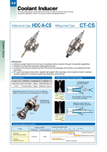 Coolant Inducer
4 Pages
 Hyper Spindle
3 Pages
 Angle Heads
7 Pages
 Keyless Drill Chucks
2 Pages
 Synchronous Tap Holder
11 Pages
 Heating Device
3 Pages
 R-Zero collet chucks
9 Pages
 New Generation Milling Chucks
15 Pages


- Chuck
- Milling chuck
- Drilling chuck
- Collet chuck
- High-precision chuck
- Collet tool holder
- Milling tool holder
- Drilling tool holder
- BT chuck
- High-precision tool holder
- Morse taper chuck
- Angle gear drives
- Tapping holder
- Quick-change chuck
- ER collet chuck
- Morse taper tool holder
- High-rigidity chuck
- BT tool holder
- High-rigidity tool holder
- Quick-change tool holder