X13
1 /4Pages

X13
1 /4Pages
Catalog excerpts

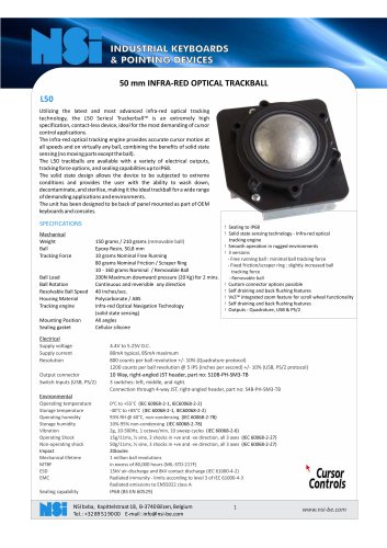
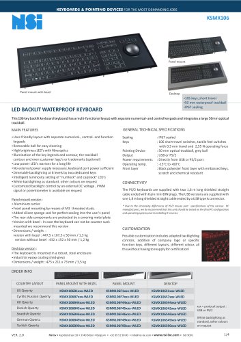
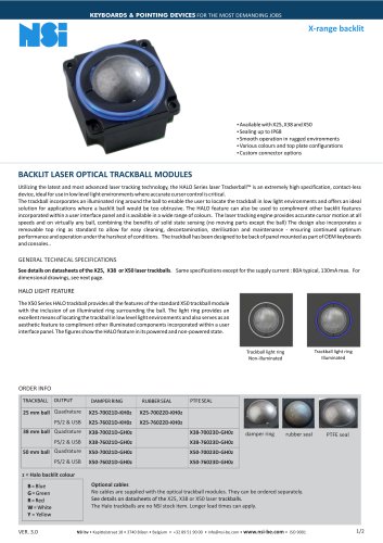
KEYBOARDS & POINTING DEVICES FOR THE MOST DEMANDING JOBS Solid state sensing technology - Laser tracking engine Sealing to IP68 Output: PS/2 & USB or Quadrature Smooth operation in rugged environments Various top plate configurations Custom connector options 13 MM OPTICAL OEM TRACKBALLMODULE Utilizing the latest and most advanced laser optical tracking technology, the X13 laser optical Trackerball™ is an extremely high specification, contactless device, ideal for the most demanding of cursor control applications. The laser tracking engine provides accurate cursor motion at all speeds and on virtually any ball, combining the benefits of solid state sensing (no moving parts except the ball). The design incorporates a removable top ring as standard to allow for easy cleaning, decontamination, sterilisation and maintenance - ensuring continued optimum performance and operation under the harshest of conditions. The X13 trackballs are available with a variety of electrical outputs, tracking force options, and sealing capabilities up to Ip68. The trackball has been designed to be back of panel mounted as part of OEM keyboards and consoles. GENERAL TECHNICAL SPECIFICATIONS Mechanical Weight Ball Tracking Force Ball Load Resolvable Ball Speed Housing Material Transducer Mounting Position Electrical Supply voltage Supply current Resolution Output connector Laser safety class Environmental Operating temperature Storage temperature Operating humidity Storage humidity Vibration Operating Shock Mechanical lifetime MTBF ESD EMC Sealing capability 15 grams Epoxy Resin, 12,7 mm 10 grams Nominal - damper ring 10 - 30 grams - rubber seal 50N Maximum downward pressure (5 Kg) for 2 mins. 40 Inches/sec. Polycarbonate (Lexan®LS2 lens grade) / ABS Optical Navigation Technology (solid state sensing) All angles (Dependant on top plate arrangement) 4.4V to 5.25V D.C. 23mA typical, 25mA maximum 300 counts per ball revolution @ 1 IPS (inches per second) +/- 10% 600 counts per ball revolution @ 5 IPS (inches per second) +/- 10% 8 Way, right-angled JST film connector, part no: 08FM-1.0SP-1.9-TF Embedded class 1M laser safety, IEC 60825-1 0°C to +55°C (IEC 60068-2-1, IEC60068-2-2) -40°C to + 85°C (IEC 60068-2-1, IEC60068-2-2) 93% RH @ 40°C, non-condensing (IEC 60068-2-78) 10%-95% non-condensing (IEC 60068-2-78) 5g, 10-500Hz, 1 octave/min, 10 sweep cycles (IEC 60068-2-6) 15g/11ms, ½ sine, 3 shocks in +ve and -ve direction, all 3 axes (IEC 60068-2-27) 1 million ball revolutions in excess of 80,000 hours (MIL-STD-217F) 15kV air-discharge and 8kV contact discharge (IEC 61000-4-2) Radiated immunity - limits according to level 3 of IEC 61000-4-3 Radiated emissions to EN55022 class B IP68 (BS EN 60529)
Open the catalog to page 1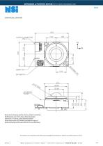
KEYBOARDS & POINTING DEVICES FOR THE MOST DEMANDING JOBS DIMENSIONAL DRAWING Dimensional drawing specifies factory default orientation. All dimensions are in mm unless otherwise stated. Tolerances +/- 0.2mm unless otherwise stated Please note that an IGES model is available on request. Please contact your local sales office for more information. The company reserves the right to alter without prior knowledge the specification or design of any standard product or service. NSI bv • Kapittelstraat 18 • 3740 Bilzen • Belgium • +32 89 51 90 00 • [email protected] • www.nsi-be.com • IS
Open the catalog to page 2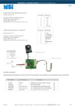
KEYBOARDS & POINTING DEVICES FOR THE MOST DEMANDING JOBS CONNECTION DETAILS QUADRATURE OUTPUT Output Connector : P1 Description: header 8 way FM 1.0mm pitch Manufacturer: JST (or equivalent) Part No: 08FM-1.0SP-1.9-TF Mating connector: Flexible flat cable (FFC), 1.0mm pitch CONNECTION DETAILS PS/2 - USB OUTPUT Left switch Middle switch Right switch GND Description: header 8 way FM 1.0mm pitch Manufacturer: JST (or equivalent) Part No: 08FM-1.0SP-1.9-TF Mating connector: Flexible flat cable (FFC), 1.0mm pitch External switch +5V DC D-, PS/2 Data D+, PS/2 Clock Right Switch Left Switch 0V Middle...
Open the catalog to page 3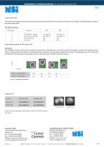
KEYBOARDS & POINTING DEVICES FOR THE MOST DEMANDING JOBS CONFIGURATION The X13 Series trackball provides features that may be selected using the DIP switch located on the printed circuit board. This table details the assigned function of each switch. DIP Switch Functions DIP Switch Orientation 1 Setting Orientation 2 Setting Factory setting Not used Factory default setting: All DIP switches OFF Orientation The orientation function allows the user to mount the X13 Series trackball device in one of four positions (see figure. 1 below). The orientation of the device is determined by the direction...
Open the catalog to page 4All NSI catalogs and technical brochures
 KSTP105
4 Pages
 L50
L506 Pages
 KSMX106
4 Pages
 Industry brochure
2 Pages
 KSML92-MC1
3 Pages
 KSME103
3 Pages
 TBS25 & SBS25
2 Pages
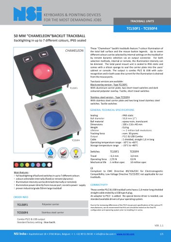 TCL50F1 - TCS50F4
5 Pages
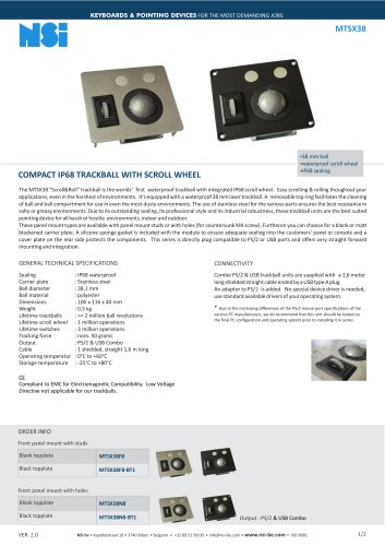 MTSX38
2 Pages
 LTSX50
3 Pages
 TSX50S8
2 Pages
 TSX38
TSX382 Pages
 TSX50
TSX503 Pages
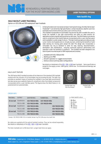 Halo backlit ring
2 Pages
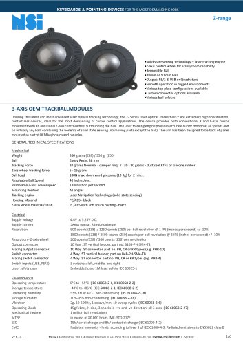 Z-range
6 Pages
 X50
X505 Pages
 KBSP106
3 Pages
 KBTS26
2 Pages
 KSML92
3 Pages
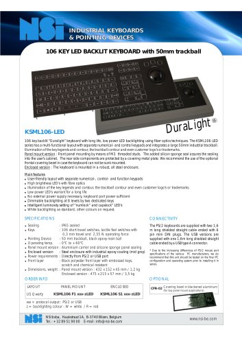 KSML106-LED
2 Pages
 KSTC36
3 Pages
 KBMT26
3 Pages
 KBMT106
3 Pages
 KSTL105
4 Pages
 l38
l387 Pages
 X38
X385 Pages
 X25
X254 Pages
 X19
X194 Pages
 X-range backlit
2 Pages
 GK75
GK752 Pages
 GS50
GS502 Pages
 GK38
GK382 Pages
 GK25
GK252 Pages
 GK16
GK162 Pages
 SPS55
SPS552 Pages
Archived catalogs
 gk25
gk252 Pages
 ksml38led
2 Pages
 x25_
x25_4 Pages
 x38
x385 Pages
 l38_optical
7 Pages
 industry brochure
4 Pages
 marine brochure
4 Pages
 military brochure
4 Pages
 Maritime catalogue
2 Pages
 Rugged catalogue
2 Pages
 Industrial catalogue
2 Pages
 NSI laser trackballs
2 Pages
 Medical catalogue
2 Pages
 NSI catalog
20 Pages


- USB keyboard
- Industrial keyboard
- Panel-mount keyboard
- Keyboard with mechanical keys
- IP65 keyboard
- Washdown keyboard
- PS2 keyboard
- Compact keyboard
- Reinforced keyboard
- Plastic keyboard
- Keyboard with touchpad
- Backlit keyboard
- Desktop keyboard
- QWERTY keyboard
- Custom keyboard
- Keyboard with Fn key
- Stainless keyboard
- Keyboard with trackball
- Metal keyboard
- Heavy-duty keyboard