
Catalog excerpts
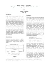
Things Your Screw Designer Never Told You About Screws!!ӔByTimothy W. WomerXaloy, Inc. Introduction L/D Ratio In the plastics industry today and as hasbeen since the start of plastic extrusion, theend user has depended on the OriginalEquipment Manufacturer (OEM) and/orscrew manufacturer to supply them with theproper screw design for their material andprocess. Most processors have learned overthe years a few critical points pertaining toscrew design, but never totallyunderstanding the reason why their suppliershave recommended certain aspects to thescrews that they have purchased. Hopefully,this paper will explain some of the basicknowledge needed in order for an end-userto make the proper decisions when using orpurchasing a new single screw for a smoothbore application. Some OEMs define their particular L/D ratio(or Length per Diameter ratio) differentlyfrom one to another. Some manufacturersdefine it as being the enclosedӔ portion ofthe screw, or they measure the flightedlength from the front side of the feed port tothe end of the screw. Some measure theflighted length from the center of the feedport opening, while others measure theactual effectiveӔ length or the entireflighted length when determining the L/Dratio. How they define the L/D ratio can beone issue, but the actual amount that thescrew manufacturer has to machine isdetermined as shown in Figure 1. Anexample how to determine the L/D of a 2.5screw would be as follows:Screw Dia. = 2.5ԔFlighted length = 63 Therefore,L/D = 63Ԕ / 2.5 = 25.2 L/DAn OEM would classify this machine as a24:1 L/D extruder, but the screwmanufacturer will typically cost it as a 25.2L/D because that is the actual amount ofmachine work which the screwmanufacturer must do to complete theproduct.Typical extruder L/Ds are 24:1 and 30 or32:1, but there are special applicationswhere extruders are built as short as 10:1L/D and as long as 50:1 L/D. The properL/D is determined by the process andapplication that is being satisfied. Nomenclature Before we get started we need to definesome of the basic components of the singleflighted screw. These terms are shown infigure 1: Flighted Length = F.L. Screw Dia. = D Feed Transition Meterin g L/D =Flighted Length (F.L.)Screw Diameter ( D ) Figure 1 > Paper presented at ANTEC 2000, the Annual Technical Conference of the Society of Plastics Engineers Inc. Copyright ԩ 2000, Society of Plastics Engineers Inc. All rights reserved. When the paper was prepared, Mr. Womer was affiliated with NewCastle Industries Inc., acquired by Xaloy in 2003. size="-2">
Open the catalog to page 1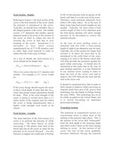
Feed Section - Depths Referring to Figure 1, the feed section of thescrew is the first element of the screw wherethe polymer is introduced to the screw.Typically, on smooth bore extruders, this isthe deepest portion of the screw. On smallerscrews, 2.5 diameters and smaller, specialattention needs to be given to this section ofthe screw in order to reduce the risk oftwisting the screw in half due to overtorquing of the screw. Sometimes it isadvisable to have small screwsmanufactured out of 17-4 Ph stainless steelor other high yield material in order toreduce the risk of this type of...
Open the catalog to page 2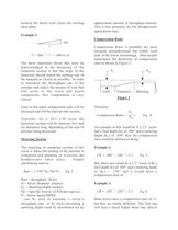
towards the barrel wall where the meltingtakes place. Example 1: Compression Ratio > .0061Ԕ Compression Ratio is probably the mostmisused, misunderstood, but widely usedterm of the screw terminology. Most peopleunderstand the definition of compressionratio as shown in Figure 2: Therefore:Compression Ratio = Eq. 4An example of this would be if a 2.5 screwhad a feed depth (h F =.006Ԕ / 1 = .006 in./in The most important factor that must beacknowledged in the designing of thetransition section is that the slope of thetransition should match the melting rate ofthe material as closely as...
Open the catalog to page 3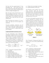
will also only have approximately 2/3 thethroughput rate. The second screw willhave a much lower shear rate and be able toprocess more shear sensitive materials and itwill have a higher throughput rate.Plus, the slope of the transition hasnt evenbeen considered in this case. Two screwscould have different compression ratios; butif the length of the transition section wasdifferent, they could still have the samemelting rates.When describing the geometry of a screw,make sure that all of the details areexamined.Accurate pumping capacities can becalculated by using more complex formulae,but a...
Open the catalog to page 4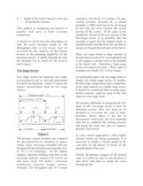
p First Second Feed Trans. Metering Dec. Vent Comp. Metering First Sta g e Second Sta g e >
Open the catalog to page 5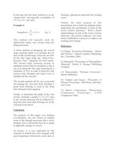
In the past this has been referred to as thepump ratioӔ and typically a multiplier of1.5:1 to 1.6:1 was used. Example 4: > == 1:6.1 Eq. 9 > hhPumpRatio mp This method will typically work forapplications where very viscous resins arebeing processed.A better method of designing the secondstage metering depth is to calculate the netflow of the second stage versus the net flowof the first stage using the Drag Flow-Pressure FlowӔ equations for best results.The second stage metering section orpumping section must be designed so that itcan over pump the first stage metering by aminimum of 25% in...
Open the catalog to page 6All Nordson Xaloy catalogs and technical brochures
-
Custom Injection Units
1 Pages
-
FTR Valves
2 Pages
-
Auto-Shut Valves
2 Pages
-
Injection Molding Screws
2 Pages
-
Pulsar® Mixing Screw
1 Pages
-
Z-Mixer? Screw
1 Pages
-
Fusion™ II screw
2 Pages
-
SmartHeat? Coating
4 Pages
-
Injection Barrels
1 Pages
-
Mini Jet Cleaner
2 Pages
-
JCP 1724 Jet Cleaner
2 Pages
-
WRP-35s/36s Pelletizer
2 Pages
-
WRP-12i In-Line Pelletizer
2 Pages
-
Static Mixers
2 Pages
-
EquaTherm® Rolls
2 Pages
-
Durashell
2 Pages
-
Standard extrusion pumps
2 Pages
-
Extrusion Barrels
1 Pages
-
X8000
1 Pages
-
Extrusions screws
2 Pages
-
Elastomer Nozzle
7 Pages
-
BHP Shutoff Nozzle
11 Pages
-
Hydraulic changers
2 Pages
-
Front-end components.
3 Pages
-
Stratablend® II
1 Pages
-
Efficient™ Extrusion Screw
1 Pages
-
Fusion™ Screw
2 Pages
-
Xaloy Extrusion equipment
1 Pages
Archived catalogs
-
Gross® Equatherm® Rolls
1 Pages
-
Nano™ Mixer
1 Pages


