NR2007
1 /29Pages

NR2007
1 /29Pages
Catalog excerpts

Temperature controller for 1 - 2 zones Operations manual Gewerbegebiet Volmershoven Am Tonschuppen 2 ■ D-53347 Alfter
Open the catalog to page 1
Operations manual Dear customer, thank you for having chosen a NOLDEN temperature controller. This high quality device has been produced in our ISO 9001-certified factory and was shipped to you after a thourough quality test. Unpack Check the device for eventual shipping damage. Don't connect damaged equipment ! Claim the damage with your shipping agent. Please read carefully this operating manual before bringing the device into service ! Connect Wiring the device should be done by your qualified electrician following the instructions given in this manual. Warranty period is 2 years and includes...
Open the catalog to page 2
Operations manual Carefull packaging is essential for a safe shipment ! Small repairs up to 80,- EUR are done immediately without formal offer. In any other case, we contact you as soon as possible to determine the next steps. To facilitate your orientation in this manual, you find the following symbols : Safety advice General information Wiring- and installing advice NOLDEN Regelsysteme GmbH
Open the catalog to page 3
Operations manual 5.3 Setting of desired temperature 5.4 Configuration level 1 = Working level : Shows powersetting, alarm values, autotuning 17 5.5 Configuration level 2 = Program level : Control mode, adaptation to controlled system, heat/cool, switching time, P-, I-, D-values, upper / lower setpoint limits, hysteresis cooling 5.6 Configuration level 3 = Program level : Manual powersetting, alarm, analog output, softstart-time, softstart-powersetting 5.7 Configuration level 4 = Program level : Key lock, thermocouple type, °C or F, offset, Power limiter, default settings NOLDEN Regelsysteme...
Open the catalog to page 4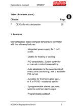
Operations manual Tabel of content (cont.) Chapter Microprocessor based compact temperature controller with the following features: - Integrated power supply for 1 or 2 zones - Usable for heating or cooling - PID-caracteristic, 2-point-controller or manual constant powersetting - Auto-adaptation to the caracteristic of every zone (autotuning) with 2 available PID-curves - Available for thermocouples type J or K or Pt100- resistance sensor - 2 programmable alarms per zone, wired to common alarm output - Programmable softstart NOLDEN Regelsysteme GmbH
Open the catalog to page 5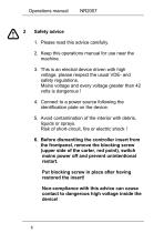
Operations manual Safety advice 1. Please read this advice carefully. 2. Keep this operations manual for use near the machine. 3. This is an electral device driven with high voltage, please respect the usual VDE- and safety regulations. Mains voltage and every voltage greater than 42 volts is dangerous ! 4. Connect to a power source following the identification plate on the device. 5. Avoid contamination of the interior with debris, liquids or sprays. Risk of short-circuit, fire or electric shock ! 6. Before dismantling the controller insert from the frontpanel, remove the blocking screw (upper...
Open the catalog to page 6
Operations manual 7. Don‘t place the device on hot machine surfaces or near radiation sources of hot parts. 8. Keep the power connection cable clear of hot parts or sharp edges. 9. Disconnect the power cable immediately, if - liquid or parts penetrated the device, - the device was damaged by falling down or other mechanical impacts, - you have the suspicion of any malfunction. 10. The operator must be thoroughly instructed by a qualified person for the work to be carried out. 11. Intervention at the device must only be carried out by qualified staff members. For repair, the device should be send...
Open the catalog to page 7
Operations manual Mains voltage : 100...240V +/- 10%, 50/60Hz Nominal rating / nominal current : Controller 2.300W / 10A per zone max. 16A with 2 zones Fuses Heaters : 10A FF, 6,3x32mm Controller : 500mA MT, 5x20mm Alarm output: Relay max. 250V/5A, common output Input : - If ordered for thermocouple : Type J or K - If ordered for resistive sensor : Pt100 2– or 3-wires Accuracy: 0,5% FS Power control 0...100% proportional, zero-voltage switching Solid state relay rated up to 50A Display : 7-segment LED-display 8mm green (actual value) and red (set-point), signal-LEDs red for output and alarm.
Open the catalog to page 8
Operations manual Soft-start Softstart-time (min) and –powersetting (0…100%) programmable. Heating- and TC-connection 6pol. + PE (1 zone) or 10-pol. +PE (2 zones) industrial heavy duty connector 16A/400V Alarm connector : 7-pol. + PE for alarm output Floating relay contacts, wired on 1 common output Dimensions : 217 x 110 x 250mm (W x H x D) Farbe: Powder coating RAL 7035 (Bottom incl. front and back) RAL 3000 (Upper casing) Environmental conditions : Degree of pollution (VG) 2 following EN610101 Ambient temperature 0 - 55°C Humidity 10 - 80% (without condensation) NOLDEN Regelsysteme GmbH
Open the catalog to page 9
Operations manual 4.1 Installation : The installation site must provide easy access for the operator without hazard. Sufficient mechanical stability must be guaranteed, also secure the device from slipping on the installation surface. Protect from heat, radiation and allow free air circulation. Protect power cable from heat and mechanical stress. Do not place the device on hot surfaces. 4.2 Connection of the power supply : This device must only be operated at the voltage indicated on the name plate. Please check for a sufficient fuse protection of the power outlet foreseen for the device. Protective...
Open the catalog to page 10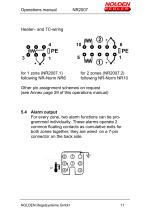
Operations manual for 1 zone (NR2007.1) following NR-Norm NR6 for 2 zones (NR2007.2) following NR-Norm NR10 Other pin assignment schemes on request (see Annex page 29 of this operations manual) 5.4 Alarm output For every zone, two alarm functions can be programmed individually. These alarms operate 2 common floating contacts as cumulative exits for both zones together, they are wired on a 7-pin connector on the back side. NOLDEN Regelsysteme GmbH
Open the catalog to page 11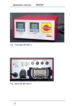
Operations manual
Open the catalog to page 12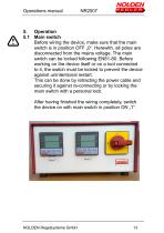
Operations manual 5. Operation 5.1 Main switch Before wiring the device, make sure that the main switch is in position OFF „0“. Herewith, all poles are disconnected from the mains voltage. The main switch can be locked following EN81-80. Before working on the device itself or on a tool connected to it, the switch must be locked to prevent the device against unintentional restart. This can be done by retracting the power cable and securing it against re-connecting or by locking the main switch with a personal lock. After having finished the wiring completely, switch the device on with main switch...
Open the catalog to page 13All Nolden Regelsysteme GmbH catalogs and technical brochures
 NT 2100
2 Pages
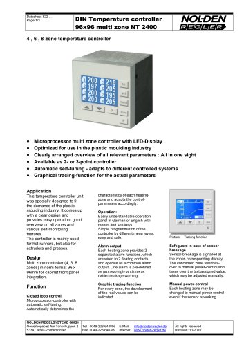 NT 2400
2 Pages
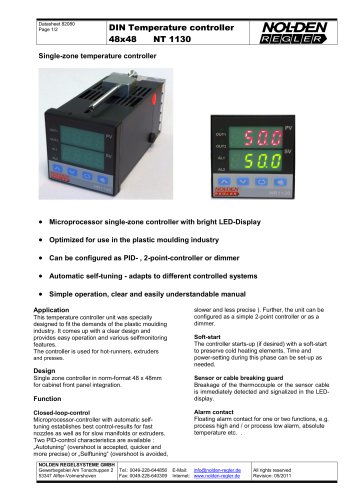 NT 1130
2 Pages
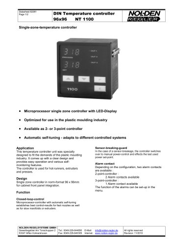 NT 1100
2 Pages
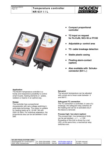 NR 631 I / L
2 Pages
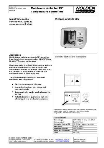 Mainframe racks for 19”
2 Pages
 NOLDEN Mould Connect
2 Pages
 Dimmer NR 507
2 Pages
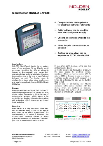 Mouldtester MOULD EXPERT
2 Pages

- Digital temperature control
- Switching relay
- Portable tester
- Digital temperature controller
- Insulation testing system
- Compact tester
- USB tester
- Digital control system
- Automatic control system
- Compact temperature control
- Electrical appliance tester
- AC solid state relay
- Single-phase solid state relay
- Temperature controller with LED display
- Automatic temperature controller
- Temperature regulator control system
- Temperature control system