way collapsed spine EVPN/VXLAN
1 /35Pages
way collapsed spine EVPN/VXLAN
1 /35Pages
Catalog excerpts
Nokia Reference Design Collapsed Spine EVPN/VXLAN Fabric Authors: Aninda Chatterjee and Vivek V © 2025 Nokia. Use subject to Terms available at: www.nokia.com/terms
Open the catalog to page 1
Collapsed Spine EVPN/VXLAN Fabric Nokia is committed to diversity and inclusion. We are continuously reviewing our customer documentation and consulting with standards bodies to ensure that terminology is inclusive and aligned with the industry. Our future customer documentation will be updated accordingly. This document includes Nokia proprietary and confidential information, which may not be distributed or disclosed to any third parties without the prior written consent of Nokia. This document is intended for use by Nokia’s customers (“You”/”Your”) in connection with a product purchased or...
Open the catalog to page 2
Collapsed Spine EVPN/VXLAN Fabric Preface for reference designs 5 4.3 MAC address and IP-MAC bindings on spines (single-homed and 5.3 Single-homed server to multihomed server (directly attached to spines) 34 6 Digital twin with Containerlab 35 Use subject to Terms available at: www.nokia.com/terms 3HE-21912-AAAA-TQZZA
Open the catalog to page 3
Collapsed Spine EVPN/VXLAN Fabric List of Figures Figure 1 Figure 2 Figure 3 Figure 4 Figure 5 © 2025 Nokia. Use subject to Terms available at: www.nokia.com/terms 3HE-21912-AAAA-TQZZA
Open the catalog to page 4
Collapsed Spine EVPN/VXLAN Fabric Preface for reference designs The main distinction between the Nokia Validated Designs (NVDs) and Nokia Reference Designs is analogous to that of a supported product versus an open-source community version of the same product. The validated designs (NVDs) are officially supported, tested on hardware, and recommended by Nokia. NVDs have a lifecycle management system, migration paths, official configuration recommendations, and support by Nokia support and services organizations. Disclaimer: Reference designs are meant to be design guides that demonstrate alternate...
Open the catalog to page 5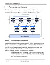
Collapsed Spine EVPN/VXLAN Fabric Reference architecture This collapsed spine reference design demonstrates an architecture with enhanced scale-out requirements, using four spines instead of the typical two, while still following the general principles of a collapsed spine design. A high-level overview of the topology is shown in Figure 1. 4-way collapsed spine high-level design This design incorporates a full-mesh connectivity between all spines for alternate paths in the case of spine-to-spine link failures. Layer 2 Top-of-rack (ToR) switches are multihomed to the spines via Ethernet segments....
Open the catalog to page 6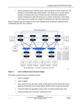
Collapsed Spine EVPN/VXLAN Fabric • Re-use of legacy Layer 2 switches (even Layer 2 switches of other vendors) as ToR switches in more modern data center designs. This allows you to connect legacy switches or switches with Layer 2 license only (thus minimizing investment in network infrastructure) while still moving into a modern architecture, which allows room to grow into a scaled-out 3-stage Clos design as and when the need arises. Figure 2 depicts a low-level design for the 4-way collapsed spine architecture, deployed using Containerlab and SR Linux container. 4-way collapsed spine low-level...
Open the catalog to page 7
Collapsed Spine EVPN/VXLAN Fabric In a collapsed spine design, the collapsed spines (spine and leaf functionality on one node) are positioned as VXLAN tunnel endpoints (VTEPs), with the Layer 2 ToR switches connecting via Ethernet segments (and link aggregation groups on the ToR side). This design provides the following two variations in how the underlay can be implemented: • External Border Gateway Protocol (eBGP) underlay using IPv6 link-local addressing and BGP dynamic neighbors • Open Shortest Path First (OSPF) unnumbered Both design variants employ full mesh Internal Border Gateway Protocol...
Open the catalog to page 8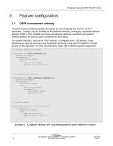
Collapsed Spine EVPN/VXLAN Fabric OSPF unnumbered underlay The point-to-point interfaces between the spines are not configured with any IPv4 or IPv6 addresses – instead, they are enabled as unnumbered interfaces, leveraging a loopback interface address. OSPF is then enabled over these unnumbered interfaces, advertising the system0 interface address for spine-to-spine reachability for the overlay. The system0 interface, used as the VTEP address, is configured with a /32 address. These addresses are used as the source and destination addresses in the outer IP header for VXLAN tunnels. In this document,...
Open the catalog to page 9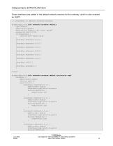
Collapsed Spine EVPN/VXLAN Fabric These interfaces are added in the default network-instance for the underlay, which is also enabled for OSPF. // interfaces in default network-instance A:admin@spine1# info network-instance default type default admin-state enable description "fabric: dc1 role: spine" router-id 192.0.2.101 ip-forwarding { receive-ipv4-check false } interface ethernet-1/1.0 { } interface ethernet-1/2.0 { } interface ethernet-1/3.0 { } interface ethernet-1/4.0 { } interface ethernet-1/5.0 { } interface ethernet-1/6.0 { } interface lo0.0 { } interface system0.0 { } *snip* A:admin@spine1#...
Open the catalog to page 10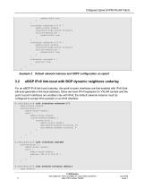
Collapsed Spine EVPN/VXLAN Fabric } interface ethernet-1/5.0 { admin-state enable interface-type point-to-point failure-detection { enable-bfd true } } interface ethernet-1/6.0 { admin-state enable interface-type point-to-point failure-detection { enable-bfd true } } interface system0.0 { passive true } enable-bfd true Default network-instance and OSPF configuration on spine1 eBGP IPv6 link-local with BGP dynamic neighbors underlay For an eBGP IPv6 link-local underlay, the point-to-point interfaces are first enabled with IPv6 (that will auto-generate a link-local address). Since we have IPv4...
Open the catalog to page 11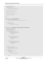
Collapsed Spine EVPN/VXLAN Fabric admin-state enable router-id 192.0.2.101 ip-forwarding { receive-ipv4-check false } interface ethernet-1/1.0 { } interface ethernet-1/2.0 { } interface ethernet-1/3.0 { } interface system0.0 { } *snip* A:admin@spine1# info routing-policy prefix-set prefixset-dc1 { prefix 192.0.2.0/24 mask-length-range 32..32 { } } policy allow-all { default-action { policy-result accept } } A:admin@spine1# info network-instance default protocols bgp admin-state enable autonomous-system 65501 router-id 192.0.2.11 dynamic-neighbors { interface ethernet-1/1.0 { peer-group bgp-underlay...
Open the catalog to page 12All Nokia catalogs and technical brochures
 Collapsed Spine EVPN VXLAN
93 Pages
 Nokia Validated Design
72 Pages