Nokia Validated Design
1 /72Pages
Nokia Validated Design
1 /72Pages
Catalog excerpts
Nokia Validated Design 3-stage EVPN/VXLAN Fabric 3HE-21632-AAAA-TQZZA Issue 1 March 2025 © 2025 Nokia. Use subject to terms available at: www.nokia.com/terms.
Open the catalog to page 1
Legal notice Nokia is committed to diversity and inclusion. We are continuously reviewing our customer documentation and consulting with standards bodies to ensure that terminology is inclusive and aligned with the industry. Our future customer documentation will be updated accordingly. This document includes Nokia proprietary and confidential information, which may not be distributed or disclosed to any third parties without the prior written consent of Nokia. This document is intended for use by Nokia’s customers (“You”/”Your”) in connection with a product purchased or licensed from any company...
Open the catalog to page 2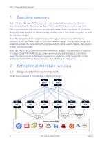
Executive summary Nokia Validated Designs (NVDs) is a workstream dedicated to producing validated recommendations to the consumer about Nokia’s portfolio across market segments. This is accomplished with extensive requirement analysis from a multitude of customers along with deep research of the technology development in the industry segment to form the solutions design. Once the design has been compiled, it goes through an intense array of hardware, software, traffic and failure tests to form the validated design. The resultant design and collateral provide the consumer with a template which...
Open the catalog to page 6
Figure 1.3-stage EVPN VXLAN NVD architecture This section describes the various components involved in this validated design and the design and technology choices that were made. • The design strategically positions multiple Nokia data center platforms at the spine and leaf layers of a 3-stage Clos fabric. The purpose of positioning multiple variants of platforms is to help the consumer make informed decisions according to their sizing, scale, and needs. • This also shows seamless interoperability with Broadcom Tomahawk platforms on the spines and Broadcom Trident platforms at the leaf layers....
Open the catalog to page 7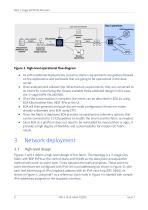
• As with traditional deployments, broad customer requirements are gathered based on the applications and workloads that are going to be operational in the data center. • Once analyzed and collated into infrastructure requirements, they are converted to an intent by customizing the closest available Nokia validated design (in this case, the 3-stage EVPN VXLAN NVD). • Once the customization is complete, the intent can be described in EDA by using EDA K8s manifest files, REST APIs or the UI. • EDA will then generate and push the per-node configuration (these are nodes already onboarded onto EDA...
Open the catalog to page 8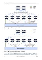
IPv6 link-local underlay with BGP dynamic neighbors Server connectivity This is an Edge-Routed Bridging (ERB) design with Integrated Routing and Bridging (IRB) interfaces configured on the leafs using a distributed anycast gateway model. All server
Open the catalog to page 9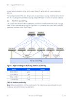
NVD 3-stage EVPN/VXLAN Fabric connectivity terminates at the leafs, where the leafs act as VXLAN tunnel endpoints (VTEPs). For routing between VNIs, this design uses an asymmetric routing model (as described in RFC 9135), along with symmetric routing using EVPN Type-5 routes for certain subnets. This section describes the Nokia platforms positioned for different roles in the 3-stage EVPN VXLAN validated design. Figure 5 provides a visual depiction while Table 1 lists all platforms and their count in the fabric. Table 1. Platform positioning Note: Alternate platforms can be positioned in the roles...
Open the catalog to page 10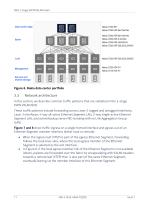
Figure 6. Nokia data center portfolio Network architecture In this section, we describe common traffic patterns that are validated in the 3-stage EVPN VXLAN NVD. These traffic patterns include forwarding across Layer 2 tagged and untagged interfaces, Layer 3 interfaces, 4-way all-active Ethernet Segment LAG, 2-way single-active Ethernet Segment LAG, and active/backup server NIC-bonding with no Link Aggregation Group (LAG). Figure 7 and 8 show traffic ingress on a single-homed interface and egress out of an Ethernet Segment member interface (either local or remote). • When the ingress leaf (VTEP)...
Open the catalog to page 11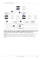
IXIA traffic generator Figure 8. Packet flow for Layer 2 tagged and untagged traffic exiting via a remote VTEP when local member interface of Ethernet Segment is down on ingress VTEP Figure 9 demonstrates traffic ingress on a 4-way all-active Ethernet Segment with the egress via a single-homed Layer 3 interface on a remote VTEP. In this case, the destination that is connected via a Layer 3 interface will be learnt using EVPN Type-5 routes.
Open the catalog to page 13
Figure 9. Packet flow for traffic ingress on a 4-way Ethernet Segment member interface directed to a destination behind a Layer 3 interface on a remote VTEP Figure 10 and Figure 11 demonstrate the traffic patterns for a destination that is behind a single-active Ethernet Segment. • Figure 10 demonstrates traffic ingress via the active VTEP of a single-active Ethernet Segment and uses local-bias forwarding rules to send out another locally attached Ethernet Segment. Figure 11 demonstrates traffic ingress on a single-homed interface. It is forwarded over the fabric by encapsulating VXLAN headers...
Open the catalog to page 14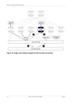
IXIA traffic generator
Open the catalog to page 15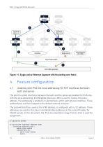
Figure 11. Single-active Ethernet Segment with forwarding over fabric Feature configuration Underlay with IPv6 link-local addressing for P2P interfaces between leafs and spines The point-to-point interfaces between the leafs and the spines are enabled for IPv6 only, with link-local addressing. IPv6 Neighbor Discovery (ND) is used to resolve the peers’ address. The addressing is enabled on subinterfaces within each physical interface. These subinterfaces are then mapped to the default network-instance. The system0 interface, used as the VTEP address, is configured with a /32 address. These addresses...
Open the catalog to page 16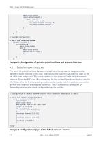
admin-state enable router-advertisement { router-role { admin-state enable max-advertisement-interval 10 min-advertisement-interval 4 } } } } } // system0 configuration A:leaf1# info interface system0 interface system0 { subinterface 0 { admin-state enable ipv4 { admin-state enable address 192.0.2.4/32 { } } } } Example 1. Configuration of point-to-point interfaces and system0 interface Default network-instance The point-to-point interfaces between the leafs and the spines are mapped to the default network-instance in SR Linux. Additionally, the system0 subinterface used as the VXLAN tunnel endpoint...
Open the catalog to page 17All Nokia catalogs and technical brochures
 way collapsed spine EVPN/VXLAN
35 Pages
 Collapsed Spine EVPN VXLAN
93 Pages