

Collapsed Spine EVPN VXLAN

Collapsed Spine EVPN VXLAN
Nokia Validated Designs (NVDs) offer validated recommendations for deploying Nokia's portfolio across various market segments. This document outlines a collapsed spine EVPN VXLAN design for a single-site, single-tiered data center architecture, using EVPN as the control plane and VXLAN as the data plane.
Design Considerations and Components
The collapsed spine topology reduces the number of devices and their capacity requirements in data centers. The document details the components and technology choices involved in this design.
High-Level Design
The document provides a high-level design overview, platform positioning, and traffic patterns for deploying the network.
This section covers the configuration of various features such as underlay with IPv6 link-local addressing, BGP for underlay and overlay routes, MTU, BFD, LLDP, and different types of interfaces including Layer 2 and Layer 3 server-facing interfaces.
The document includes a feature validation matrix and traffic convergence results to ensure the design's reliability and performance.
This section describes the EDA architecture and workflows for deploying the fabric, including node onboarding, ASN pool creation, and fabric creation.
Network and EDA validation processes are detailed to ensure the design meets the required standards.
The document discusses the use of digital twins with Containerlab for automation and orchestration purposes.
- eda-asvr: Artifact server for storing common artifacts.
- eda-bsvr: Bootstrap server for node onboarding and lifecycle management.
- eda-ce: Configuration engine for managing application dependencies and intents.
- eda-npp: Responsible for schema validation and device communication.
- eda-api: REST API server for user access and GUI consumption.
- eda-toolbox: Provides tools for EDA transactions and topology generation.
The document outlines the orchestration of a collapsed spine EVPN VXLAN fabric using EDA with IPv6 link-local addressing and MP-BGP peering. Key inputs include IP and ASN pools, label selectors, and interswitch links. BFD is enabled for fast failover on point-to-point interfaces.
Bridge domains are instantiated as MAC VRFs on SR Linux nodes. Two types are created: EVPN VXLAN BDs for collapsed spine nodes and simple BDs for ToR switches. EVPN VXLAN BDs map to VXLAN VNI and EVPN instance, enabling EVPN learning.
IRB interfaces facilitate routing between Layer 2 VNIs in EVPN VXLAN deployments. The document provides a manifest for creating IRB interfaces, highlighting the importance of enabling Layer 3 proxy-ARP for stretched VLANs.
IP VRFs are created with a 1:1 mapping to Layer 3 VNIs and EVIs. VRF creation is based on bridge domains referencing the IP VRF.
The document demonstrates VLAN creation for both untagged and tagged Layer 2 deployments, with label selectors determining interface deployment.
Routed interfaces are created using a manifest, specifying ARP timeout, interface, IP MTU, and IP addresses.
EDA allows logical separation of resources into namespaces, which must be referenced in manifest files.
Configlets allow user-defined configurations, such as ARP/ND advertisement, system-wide MTU settings, and system logging for SR Linux subsystems.
The topology manifest can be updated to include labels for ToR switches, allowing accurate visualization of the collapsed spine design.
Node profiles, ASN pools, and IP pool creation are managed through the EDA UI, facilitating node onboarding and resource allocation.
- Various VLANs and bridge domains are listed with their operational states, such as 'up' or 'degraded'.
- IRB interfaces are detailed with MTU settings and operational states, all marked as 'up'.
- IRB interfaces are configured with specific ARP timeout settings, IP addresses, and proxy settings.
- Operational states and last change timestamps are provided for each interface.
- Details of VRF configurations, including VNI, EVI, and operational states, are provided.
- EDA transactions are listed with their results, indicating successful operations over a period of 8 days.
- Digital twins are used for continuous validation and learning, with deployment scripts available for setting up a collapsed spine EVPN VXLAN fabric.
- Deployment and destruction scripts are provided for managing the digital twin environment.
- Differences between Nokia Validated Designs (NVDs) and reference designs are explained.
- Reference designs are available for exploration and testing, with repositories accessible on GitHub.
Catalog excerpts
3HE-21913-AAAA-TQZZA Issue 1 July 2025 © 2025 Nokia. Use subject to Terms available at: www.nokia.com/terms
Open the catalog to page 1
Collapsed Spine EVPN VXLAN Nokia is committed to diversity and inclusion. We are continuously reviewing our customer documentation and consulting with standards bodies to ensure that terminology is inclusive and aligned with the industry. Our future customer documentation will be updated accordingly. This document includes Nokia proprietary and confidential information, which may not be distributed or disclosed to any third parties without the prior written consent of Nokia. This document is intended for use by Nokia’s customers (“You”/”Your”) in connection with a product purchased or licensed...
Open the catalog to page 2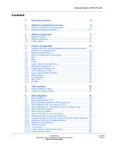
Collapsed Spine EVPN VXLAN 2 Reference architecture overview 6 4.1 Underlay with IPv6 link-local addressing for point-to-point interfaces 6.3.7 Onboarding nodes in EDA with using a TopoNode Custom Resource .. 48 Use subject to Terms available at: www.nokia.com/terms
Open the catalog to page 3
Use subject to Terms available at: www.nokia.com/terms
Open the catalog to page 4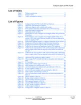
Collapsed Spine EVPN VXLAN Figure 7 Packet flow for Layer 2 tagged and untagged traffic using local bias Figure 8 Packet flow for Layer 2 tagged and untagged traffic exiting via a remote VTEP when local member interface of Ethernet segment is Figure 9 Packet flow between tagged or untagged interfaces across spines 14 Figure 13 Traffic flow for source behind ToR communicating with a destination behind single-active Ethernet segment when packet is hashed to Figure 14 Traffic flow for source behind ToR communicating with a destination behind single-active Ethernet segment when packet is hashed to...
Open the catalog to page 5
Collapsed Spine EVPN VXLAN Executive summary Nokia Validated Designs (NVDs) is a workstream dedicated to producing validated recommendations to the consumer about Nokia’s portfolio across market segments. NVDs are accomplished with extensive requirement analysis from a multitude of customers along with deep research of the technology development in the industry segment to form the solution’s design. After the design has been compiled, it goes through an intense array of hardware, software, traffic, and failure tests to form the validated design. The resultant design and collateral provide the...
Open the catalog to page 6
Collapsed Spine EVPN VXLAN This section describes the various components involved in this validated design and the design and technology choices that were made. In general, a collapsed spine design provides the following advantages: • reduction of the required number of devices and capacity of the devices in data centers where the scale-out and size of the data center are known to be limited and the main considerations become cost and power utilization • re-use of legacy Layer 2 switches (even Layer 2 switches of other vendors) as top of rack (ToR) switches in more modern data center designs...
Open the catalog to page 7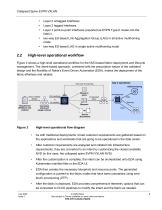
Collapsed Spine EVPN VXLAN Layer 2 untagged interfaces two-way ES-based Link Aggregation Group (LAG) in all-active multihoming mode two-way ES-based LAG in single-active multihoming mode Layer 2 tagged interfaces Layer 3 point-to-point interfaces (exported as EVPN Type-5 routes into the fabric) High-level operational workflow Figure 2 shows a high-level operational workflow for the NVD-based fabric deployment and lifecycle management. The intent-based approach, combined with the prescriptive nature of the validated design and the flexibility of Nokia’s Event Driven Automation (EDA), makes the...
Open the catalog to page 8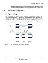
Collapsed Spine EVPN VXLAN • Because EDA as a platform does not need to be reinstalled for new patches or apps, it provides a high degree of flexibility and customizability for modern DC fabric needs. Figure 3 shows a high-level design of the fabric. The topology is a collapsed spine fabric with BGP EVPN as the control plane and VXLAN as the data plane encapsulation method with point-to-point layer 3 links between the two spines. These point-to-point interfaces are configured with IPv6-link local addressing (as shown in Figure 3), with each spine advertising its IPv4 loopback address with an...
Open the catalog to page 9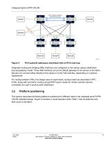
Collapsed Spine EVPN VXLAN Figure 4 IPv4 systemO addresses advertised with an IPv6 next-hop Integrated routing and bridging (IRB) interfaces are configured on the spines using a distributed anycast gateway model. These IRB interfaces act as the default gateway for all servers in the fabric. Servers can connect either directly to the spines or to the ToR switches, depending on customer requirement. For routing between VNIs, this design uses an asymmetric routing model (as described in RFC 9135), along with symmetric routing using EVPN Type-5 routes for certain subnets (servers connected via Layer...
Open the catalog to page 10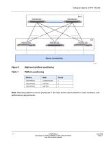
Table 1 Platform positioning Note: Alternate platforms can be positioned in the roles shown above based on cost, hardware, and performance requirements. July 2025 Issue 1 Use subject to Terms available at: www.nokia.com/terms
Open the catalog to page 11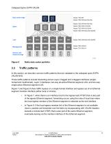
Collapsed Spine EVPN VXLAN Nokia data center portfolio Traffic patterns In this section, we describe common traffic patterns that are validated in the collapsed spine EVPN VXLAN NVD. These traffic patterns include forwarding across Layer 2 tagged and untagged interfaces (singlehomed and multihomed), Layer 3 interfaces, two-way all-active Ethernet segment LAG, and two-way single-active Ethernet segment LAG. Figure 7 and Figure 8 show traffic ingress on a single-homed interface and egress out of an Ethernet segment member interface (either local or remote). In Figure 7, when there is an interface...
Open the catalog to page 12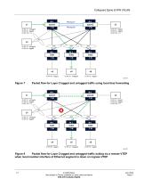
VLAN 10-tagged VLAN 30 - tagged VLAN 100-L3 VLAN 10 - untagged VLAN 20 - tagged VLAN 100-L3 _ VLAN 10 - untagged VLAN 40 - tagged Figure 7 Packet flow for Layer 2 tagged and untagged traffic using local bias forwarding spine2 VLAN 10-tagged VLAN 30 - tagged VLAN 100-L3 £> spinel VLAN 10 - untagged VLAN 20 - tagged VLAN 100-L3 _ VLAN 10 - untagged VLAN 40 - tagged Figure 8 Packet flow for Layer 2 tagged and untagged traffic exiting via a remote VTEP when local member interface of Ethernet segment is down on ingress VTEP July 2025 Issue 1 Use subject to Terms available at: www.nokia.com/terms
Open the catalog to page 13All Nokia catalogs and technical brochures
 way collapsed spine EVPN/VXLAN
35 Pages
 Nokia Validated Design
72 Pages