- Catalogs
- NKK Switches
- UB Series
UB Series
1 /12Pages

UB Series
1 /12Pages
Catalog excerpts

Series UB Low Profile Pushbuttons Electrical Capacity (Resistive Load) Power Level (silver): 5A @ 125/250V AC or 5A @ 30V DC Logic Level (gold): 0.4VA maximum @ 28 V AC/DC maximum (Applicable Range 0.1mA ~ 0.1A @ 20mV ~ 28V) Note: Find additional explanation of operating range in Supplement section. Other Ratings Contact Resistance: Insulation Resistance: Dielectric Strength: Mechanical Life: Electrical Life: Nominal Operating Force: Contact Timing: Travel: 50 milliohms maximum for silver; 100 milliohms maximum for gold 200 megohms minimum @ 500V DC 1,000V AC minimum between contacts for 1 minute minimum; 1,500V AC minimum between contacts & case for 1 minute minimum 1,000,000 operations minimum for momentary; 200,000 operations minimum for alternate action 10,000 operations minimum for silver; 100,000 operations minimum for silver with resistive load of 3A @ 125V AC 200,000 operations minimum for gold Single Pole: 1.9N for Square & 1.9N for Rectangular Double Pole: 2.55N for Square & 3.1N for Rectangular Break before make Pretravel .067" (1.7mm); Overtravel .024" (0.6mm); Total Travel .091" (2.3mm) Materials & Finishes Housing/Bezel: Snap-in Frame: Movable Contactor: Movable Contacts: Stationary Contacts: Switch Terminals: Lamp Terminals: Base: Glass fiber reinforced polyamide (UL94V-0) Stainless steel Phosphor bronze Silver alloy or copper with gold plating Silver alloy or copper with gold plating Phosphor bronze with silver or gold plating Brass with silver plating Glass fiber reinforced liquid crystal polymer (UL94V-0) Environmental Data Operating Temperature Range: Humidity: Vibration: -25°C through +50°C (-13°F through +122°F) for Illuminated -20°C through +70°C (-4°F through +158°F) for Nonilluminated 90 ~ 95% humidity for 96 hours @ 40°C (104°F) 10 ~ 55Hz with peak-to-peak amplitude of 1.5mm traversing the frequency range & returning in 1 minute; 3 right angled directions for 2 hours 50G (490m/s2) acceleration (tested in 6 right angled directions, with 5 shocks in each direction) Installation Cap Installation Force: Soldering Time & Temp: Cleaning: Standards & Certifications Flammability Standards: UL: 7.55N (1.70 lbf) maximum downward force on cap Wave Soldering (PC version): See Profile A in Supplement section. Manual Soldering: See Profile A in Supplement section. These devices are not process sealed. Hand clean locally using alcohol based solution. UL94V-0 housing/bezel & base File No. E44145 - Recognized only when ordered with marking on switch. Add "/U" or "/CUL" before dash in part number to order UL recognized switch. UL recognized only when ordered switch body with cap assembled. All single & double pole models recognized at 5A @ 125/250V AC or 0.014A @ 28V DC. File No. 023535_0_000 - Certified only when ordered with marking on switch. Add "/C" before dash in part number to order CSA certified switch. All single & double pole models certified at 5A @ 125/250V AC or 5A @ 30V DC or 0.4VA maximum @ 28 V AC/DC maximum.
Open the catalog to page 1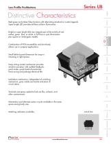
Low Profile Pushbuttons Series UB Distinctive Characteristics Red/green and amber/blue bicolors with alternating standard or custom legends. Super bright LED provides brilliant uniform illumination. Low Profile Pushbuttons Series UB Bright or super bright LEDs (an integral part of the switch) of red, amber, green, blue, or white, in full face or spot illumination plus square or rectangular models. Combination of PCB mountability and short body allows use in compact applications. Small behind panel dimension for snap-in mounting in tight spaces. Snap-acting contact mechanism provides sensitive...
Open the catalog to page 2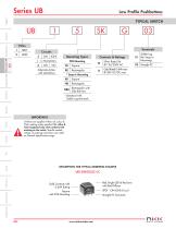
Series UB Low Profile Pushbuttons * Standard with Solder Lug terminals IMPORTANT: Switches are supplied without UL, cULus & CSA marking unless specified. UL, cULus & CSA recognized only when ordered with marking on the switch. Specific models, ratings, & ordering instructions are noted on General Specifications page. DESCRIPTION FOR TYPICAL ORDERING EXAMPLE Gold Contacts with 0.4VA Rating Square with PCB Mounting Red, Bright LED & Red Lens with Red Diffuser SPDT ON-(ON) Circuit Straight PC Terminals
Open the catalog to page 3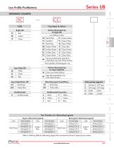
Low Profile Pushbuttons ORDERING EXAMPLE Cap Types & Colors Full Face Illuminated Cap for Bright LED Square & Rectangular Spot Illuminated Black Cap with White Window * Not available with Rectangular cap Clear Lens/White Diffuser Full Face Illuminated Cap for Super Bright LED Spot Illuminated Black Cap with White Window Alternating Legend Cap/Diffuser Super Bright Bicolor LED Alternating Legends Rectangular Alternating Legends Part Number Part Number Amber/ Blue Refer to Ordering Table for Alternating Legend that corresponds with last 2 digits of part number. Part Number Square Alternating Legends...
Open the catalog to page 4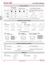
Series UB Low Profile Pushbuttons POLES & CIRCUITS * When in latchdown position for the alternate circuit, cap position is .039" (1.0mm) above the housing. MOUNTING TYPES & SHAPES PCB Mounting O 0 cs. Double Pole Single Pole Double Pole Rectangular with Built-in Side Barriers CO Snap-in Mounting (Solder Lug) Logic Level 0.4VA maximum @ 28V AC/DC maximum Complete explanation of operating range in Supplement section.
Open the catalog to page 5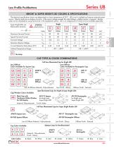
BRIGHT & SUPER BRIGHT LED COLORS & SPECIFICATIONS Super Bright Maximum Forward Current Typical Forward Current Forward Voltage Maximum Reverse Voltage Current Reduction Rate Above 25°C Full Face Illuminated Cap for Bright LED Lens/Diffuser Colors Available for Rectangular Cap: Lens & Diffuser Material: Polycarbonate Lens Finish: Glossy Diffuser Finish: Textured Spot Illuminated Caps for Bright & Super Bright LEDs Cap/Window Colors Available: Lens/Diffuser Colors Available for Square Cap: CAP TYPES & COLOR COMBINATIONS Black Cap with Translucent White Window for LED Display Material: Polycarbonate...
Open the catalog to page 6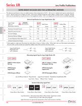
Series UB Low Profile Pushbuttons Series UB Low Profile Pushbuttons SUPER BRIGHT BICOLOR LEDS FOR ALTERNATING LEGENDS The electrical specifications shown are determined at a basic temperature of 25°C. LED circuit is isolated and requires external power source. Polarity marks are on bottom of switch. If the source voltage exceeds the rated voltage, a ballast resistor is required. Resistor value can be calculated by using the formula in the Supplement section. LED is an integral part of switch and not available separately. Electrical Specifications for Super Bright Bicolor LEDs * Value applies...
Open the catalog to page 7All NKK Switches catalogs and technical brochures
 A Indicators
2 Pages
 Series FT
15 Pages
 KP Series RGB Expansion
8 Pages
 MS series
4 Pages
 SCB-Series
3 Pages
 WB series
4 Pages
 YB series
14 Pages
 YB2
YB213 Pages
 Supplement
33 Pages
 Accessories & Hardware
33 Pages
 Rotaries
46 Pages
 Product Overview
6 Pages
 SmartSwitch
8 Pages
 Illuminated Pushbuttons
116 Pages
 Rockers
118 Pages
 Toggles
119 Pages
 Pushbuttons
130 Pages
 Rockers 2013
16 Pages
 M2 series
7 Pages
 M series
12 Pages
 G series
4 Pages
 D2 series
10 Pages
 BB series
6 Pages
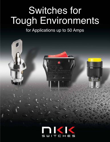 Switches for Tough Environments
12 Pages
 SMT DIP Rotaries
6 Pages
 Indicators
31 Pages
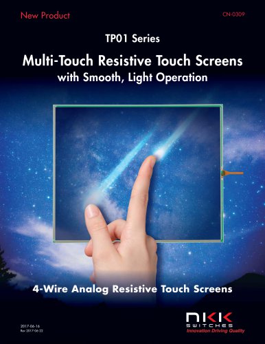
 Touch Screens
17 Pages
 Tilt Sensors
6 Pages
 Tactiles
47 Pages
 Slides
53 Pages
 Keylocks
23 Pages
 SmartSwitch
48 Pages
 Illuminated Pushbuttons
113 Pages
 Pushbuttons
130 Pages


Archived catalogs
 Tilt Electrical Ratings
1 Page
 SMT Electrical Ratings
1 Page
 Slide Electrical Ratings
1 Page
 Tactile Electrical Ratings
1 Page
 Toggle Electrical Ratings
1 Page


- Single-pole switch
- Push-button switch
- Technology switch
- Multipole switch
- Electromechanical switch
- Rocker switch
- IP67 switch
- Illuminated push-button switch
- Touch push-button switch
- Touch switch
- Action push-button switch
- Form push-button switch
- IP65 push-button switch
- Hermetic switch
- Momentary push-button switch
- Technology push-button switch
- Electromechanical push-button switch
- Metal push-button switch
- Lever switch
- Plastic push-button switch