- Catalogs
- NKK Switches
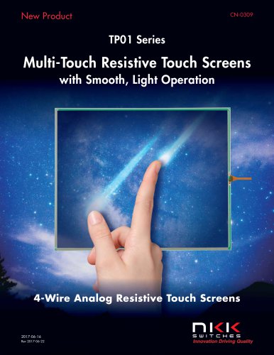
- TP01 Series Multi-Touch Resistive Touch Screens with Smooth, Light Operation
- Products
- Catalogs
- News & Trends
- Exhibitions
TP01 Series Multi-Touch Resistive Touch Screens with Smooth, Light Operation
1 /16Pages
TP01 Series Multi-Touch Resistive Touch Screens with Smooth, Light Operation
1 /16Pages
Catalog excerpts

4-Wire Analog Resistive Touch Screens
Open the catalog to page 1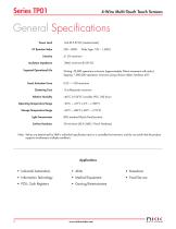
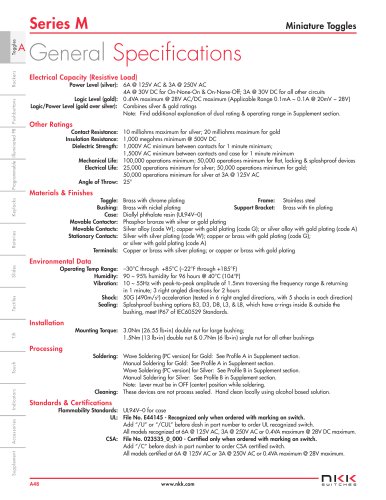
Series TP01 4-Wire Multi-Touch Touch Screens Power Level XY Resistive Value Linearity Insulation Impedance Expected Operational Life Touch Activation Force Chattering Time Relative Humidity Operating Temperature Range Storage Temperature Range Light Transmission Surface Hardness 1mA @ 5.5V DC (resistive load) 250 ~ 8500 Wide Type: 120 ~ 1,5000 ±1.5% maximum 10M0 minimum @ 25V DC Writing: 50,000 operations minimum (approximately 30mm movement with stylus) Tapping: 1,000,000 operations minimum (using silicone rubber, hardness 60°) 0.02 ~ 1.0N maximum 10 milliseconds maximum +40°C (+104°F), humidity...
Open the catalog to page 2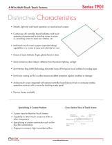
4-Wire Multi-Touch Touch Screens Distinctive Characteristics • Smooth, light and multi-touch operation on resistive touch screens • Combining with controller board facilitates multi-touch operation characterized by pinching screen to zoom in, spreading screen to zoom out, rotation, etc. • Multi-touch touch screens support expanded design capabilities in a variety of sizes and relatively low cost • Choice of input methods: finger, gloved hand or stylus • Glare resistant surface reduces reflection from fluorescent lighting, sunlight • Anti-Newton Ring (ANR) Technology eliminates many of the typical...
Open the catalog to page 3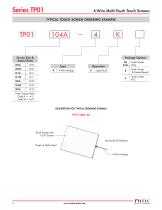
4-Wire Multi-Touch Touch Screens TYPICAL TOUCH SCREEN ORDERING EXAMPLE Screen Size & Aspect Ratio 104A Package Options Light Touch Touch Screen & Control Board Note: Aspect Ratio Code A = 4:3 Code W = 16:9 DESCRIPTION FOR TYPICAL ORDERING EXAMPLE Touch Screen with 10.4" Screen Horizontal Tail Position Finger or Stylus Input Touch Screen Only
Open the catalog to page 4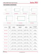
4-Wire Multi-Touch Touch Screens Series TP01 4-Wire Analog Touch Screens
Open the catalog to page 5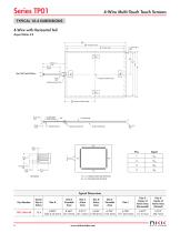
4-Wire Multi-Touch Touch Screens TYPICAL 10.4 DIMENSIONS 4-Wire with Horizontal Tail Aspect Ratio 4:3 See Tail Detail Below Center of Active Area G Center of Active Area Contact Side (Gold Plating) Reinforcement Film Bottom Electrode YUP, YLO: Bottom Electrode Terminal XLE, XRI : Top Electrode Terminal Tail Detail Typical Dimensions Part Number Dim G Center of Active Area (Horizontal) Dim H Center of Active Area (Vertical) Screen Size in Inches 10.4
Open the catalog to page 6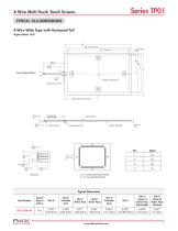
4-Wire Multi-Touch Touch Screens OPTIONAL ACCESSORIES TYPICAL 10.6 DIMENSIONS 4-Wire Wide Type with Horizontal Tail Aspect Ratio 16:9 See Tail Detail Below Center of Active Area Reinforcement Film Contact Side (Gold Plating) Center of Active Area Bottom Electrode Reinforcement Film YLO YUP, YLO: Bottom Electrode Terminal XLE, XRI : Top Electrode Terminal Tail Detail Typical Dimensions Part Number Screen Size in Inches Dim G Center of Active Area (Horizontal) Dim H Center of Active Area (Vertical)
Open the catalog to page 7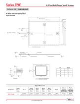
Series TP01 4-Wire Multi-Touch Touch Screens Contact Side (Gold Plating) Reinforcement Film Bottom Electrode Pins Signal Tail Detail Yup, Ylo: Bottom Electrode Terminal Typical Dimensions Part Number
Open the catalog to page 8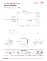
4-Wire Multi-Touch Touch Screens TYPICAL 12.1 DIMENSIONS 4-Wire Wide Type with Horizontal Tail Aspect Ratio 16:9 See Tail Detail Below Center of Active Area G Center of Active Area Contact Side (Gold Plating) Reinforcement Film Bottom Electrode YUP, YLO: Bottom Electrode Terminal XLE, XRI : Top Electrode Terminal Tail Detail Typical Dimensions Part Number Screen Size in Inches Dim G Center of Active Area (Horizontal) Dim H Center of Active Area (Vertical)
Open the catalog to page 9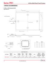
4-Wire Multi-Touch Touch Screens TYPICAL 15.0 DIMENSIONS 4-Wire with Horizontal Tail Aspect Ratio 4:3 See Tail Detail Below Center of Active Area G Center of Active Area Contact Side (Gold Plating) Reinforcement Film Bottom Electrode Tail Detail YUP, YLO: Bottom Electrode Terminal XLE, XRI : Top Electrode Terminal Typical Dimensions Part Number Screen Size in Inches 15.0 Dim G Center of Active Area (Horizontal) Dim H Center of Active Area (Vertical)
Open the catalog to page 10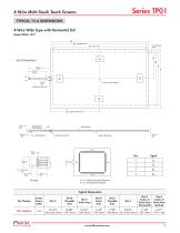
4-Wire Multi-Touch Touch Screens TYPICAL 15.6 DIMENSIONS 4-Wire Wide Type with Horizontal Tail Aspect Ratio 16:9 See Tail Detail Below Center of Active Area G Center of Active Area Contact Side (Gold Plating) Reinforcement Film Bottom Electrode YUP, YLO: Bottom Electrode Terminal XLE, XRI : Top Electrode Terminal Tail Detail Typical Dimensions Part Number Screen Size in Inches Dim G Center of Active Area (Horizontal) Dim H Center of Active Area (Vertical)
Open the catalog to page 11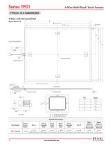
Series TP01 4-Wire Multi-Touch Touch Screens See Tail Detail Below Contact Side (Gold Plating) Center of Active Area G Center of Active Area Reinforcement Film Tail Detail Yup, Ylo: Bottom Electrode Terminal Typical Dimensions Part Number
Open the catalog to page 12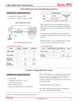
4-Wire Multi-Touch Touch Screens Series TP01 4-Wire Multi-Touch Screen Controller Boards & Drivers Recommended Values DISTINCTIVE CHARACTERISTICS • Interface: USB • Compatible with 1Windows 7, 8 & 10 IC Chip for Analog Multi-Touch Screens The IC is for use with the 4-wire transparent touch screens. When the screen is touched, it recognizes the position of the touch by the level of analog voltage detected by the A/D. The A/D converter receives the value and sends a set of coordinate values as serial data or USB. • High Speed and Accuracy • Built-in Calibration Function Contact NKK Switches...
Open the catalog to page 13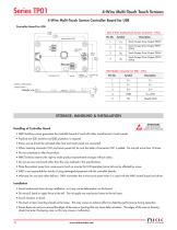
Series TP01 4-Wire Multi-Touch Touch Screens CN1 4-Wire Analog Touch Screen Connector - 4 Pins STORAGE, HANDLING & INSTALLATION ATTENTION ELECTROSTATIC SENSITIVE DEVICES Handling of Controller Board • NKK Switches cannot guarantee the controller boards if used with other manufacturer's touch panels. • Products are ESD sensitive and ESD protection is required. • Power source should be activated after host and touch panel are connected. • When inserting connector CN1 and touch panel tail, be sure the slider of connector CN1 is pulled. Do not pull more than 10 times. • Do not customize or alter...
Open the catalog to page 14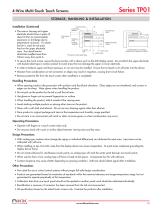
4-Wire Multi-Touch Touch Screens STORAGE, HANDLING & INSTALLATION Installation (Continued) • The case or housing and upper electrode should have a space of about 0.5mm to accommodate expansion or shrinkage due to temperature variances. If a shock barrier is used, do not press hard on the upper electrode area. Any shock barrier should be installed more than 0.6mm away from point A. Case/Housing Cushioning Material (0.5) Approx. .020 Adhesive Layer * Sealing Material Bottom Electrode (Glass) Active Area Visible Area Example of Burr on Housing Interferes with Operation at Point A * Example: Double-sided...
Open the catalog to page 15All NKK Switches catalogs and technical brochures
 A Indicators
2 Pages
 Series FT
15 Pages
 KP Series RGB Expansion
8 Pages
 MS series
4 Pages
 SCB-Series
3 Pages
 UB Series
12 Pages
 WB series
4 Pages
 YB series
14 Pages
 YB2
YB213 Pages
 Supplement
33 Pages
 Accessories & Hardware
33 Pages
 Rotaries
46 Pages
 Product Overview
6 Pages
 SmartSwitch
8 Pages
 Illuminated Pushbuttons
116 Pages
 Rockers
118 Pages
 Toggles
119 Pages
 Pushbuttons
130 Pages
 Rockers 2013
16 Pages
 M2 series
7 Pages
 M series
12 Pages
 G series
4 Pages
 D2 series
10 Pages
 BB series
6 Pages
 Switches for Tough Environments
12 Pages
 SMT DIP Rotaries
6 Pages
 Indicators
31 Pages
 Touch Screens
17 Pages
 Tilt Sensors
6 Pages
 Tactiles
47 Pages
 Slides
53 Pages
 Keylocks
23 Pages
 SmartSwitch
48 Pages
 Illuminated Pushbuttons
113 Pages
 Pushbuttons
130 Pages


Archived catalogs
 Tilt Electrical Ratings
1 Page
 SMT Electrical Ratings
1 Page
 Slide Electrical Ratings
1 Page
 Tactile Electrical Ratings
1 Page
 Toggle Electrical Ratings
1 Page


- Single-pole switch
- Push-button switch
- Technology switch
- Multipole switch
- Electromechanical switch
- Rocker switch
- IP67 switch
- Illuminated push-button switch
- Touch push-button switch
- Touch switch
- Action push-button switch
- Form push-button switch
- IP65 push-button switch
- Hermetic switch
- Momentary push-button switch
- Technology push-button switch
- Electromechanical push-button switch
- Metal push-button switch
- Lever switch
- Plastic push-button switch