- Catalogs
- NKK Switches
- Supplement
- Products
- Catalogs
- News & Trends
- Exhibitions
Supplement
1 /33Pages

Supplement
1 /33Pages
Catalog excerpts
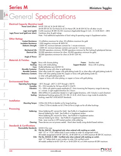
Temperature Linear Dimensions Force & Torque Plating Thickness Weight Electrical Ratings Rerating Current Inductive DC Loads; TV Ratings Operating Range & Dual Ratings Lamps & LEDs Rerating Application Considerations Ballast Resistor Calculations & Recommendations Processing Data Processing Recommendation Guide Process Sealed Switches; Automated Cleaning Specifications Manual Solder – Profiles A, B Wave Solder for Through Hole – Profiles A, B Reflow Solder for SMT – Profiles A, B Standards & Approvals UL Recognition, cULus Recognition, CSA Certification VDE, SEMKO, SEV, ISO, IP Plastics & Elements Touch Terms & Acronyms Terms & Acronyms Federal Supply Code Product Overview Ultra-Miniature, Subminiature, Miniature, Specialty, Illuminated, Standard & High Capacity
Open the catalog to page 1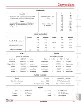
Conversions TEMPERATURE Celsius International thermometric scale with fixed points marked 0°C for freezing point and 100°C for boiling of water. Thermometric scale with fixed points marked 32°F for freezing point and 212°F for boiling of water. LINEAR DIMENSIONS PLATING THICKNESS
Open the catalog to page 2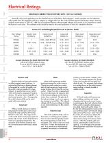
Electrical Ratings RERATING CURRENT FOR SWITCHES WITH 125V AC RATINGS Generally, most switch applications can be classified into one of the below load categories. Switch capacities can be mathematically rerated when the application calls for a category or voltage other than the switch standard general specification ratings, meaning original current ratings at 125V AC. NKK has not conducted life tests at these rerated voltages and currents so it is important to contact the factory in such cases. The candidate switch should be tested in the actual application in which it is intended to function....
Open the catalog to page 3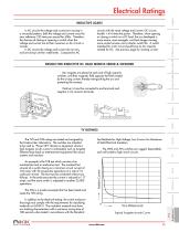
Electrical Ratings INDUCTIVE LOADS circuits with the same voltage and current, DC circuits handle 1.414 times the power. Therefore, when opening or closing a switch on a DC load, the arc developed is more severe, more energetic, and lasts longer causing more contact erosion and a shorter switch life. A switch intended for a DC circuit should have its AC capacity rerated for DC. See previous page for rerating current. In AC circuits the voltage and current are varying in a sinusoidal pattern; both the voltage and current cross the zero reference 120 times per second for 60Hz. Therefore, the chances...
Open the catalog to page 4
Electrical Ratings OPERATING RANGE Three contact materials are commonly used in NKK switches: gold, silver, and gold over silver. These materials give the options of low level, power level, plus combined power and low level ratings. Gold plated contacts are recommended for dry circuits, which are defined as very low energy. In circuits where the voltage is below 28 volts DC and current is below 100 milliamps (dry circuits), no arc develops as the contacts open or close. So, the tarnish remains. Eventually without the arc, the contacts become so encrusted that the switch is unable to close the...
Open the catalog to page 5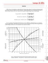
Lamps & LEDs RERATING Rated Voltage [ ] Applied Voltage Applied Voltage [ ] Rated Voltage Applied Voltage [ ] Rated Voltage Tilt Touch AVERAGE LIFE (Multiplying Factor) 80 90 100 110 120 PERCENT RATIO OF DESIGN VOLTS CURRENT and MSCP (Multiplying Factor) CURRENT and MSCP (Multiplying Factor) AVERAGE LIFE (Multiplying Factor) For your convenience, the graph below illustrates the way current, candlepower, and life performance vary with percent changes in applied voltage. The graphed values are typical for miniature and subminiature lamps with the average life based on rated voltages at 60 cycles...
Open the catalog to page 6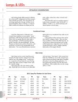
Lamps & LEDs APPLICATION CONSIDERATIONS LEDs green, yellow, amber, blue, white, or bicolor (red/ green) LEDs. Most of the LEDs used in our products require a ballast resistor connected in series with the LED. In addition, we offer 5-, 12-, and 24-volt lamps with internal resistors in the YB series. Light emitting diodes (LEDs) operate at relatively low current and DC voltage levels and have comparatively unlimited service life. Their characteristics do not change significantly with age, and they are not easily damaged by shock or vibration. A variety of NKK’s switches and indicators are offered...
Open the catalog to page 7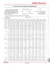
Ballast Resistors BALLAST RESISTOR CALCULATIONS & RECOMMENDATIONS R = IF Resistor Value (Ohms) Source Voltage (V) Forward Voltage (V) Forward Current (A) R If the source voltage is greater than the rated voltage of a lamp or LED, a ballast resistor must be connected in series with the lamp. The following circuit diagram and formula will assist in calculating the value of the required ballast resistor. Watt recommendations provide a margin to reduce heat rise and increase life. SOURCE VOLTAGE E
Open the catalog to page 8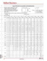
Ballast Resistors BALLAST RESISTOR CALCULATIONS & RECOMMENDATIONS R If the source voltage is greater than the rated voltage of a lamp or LED, a ballast resistor must be connected in series with the lamp. The following circuit diagram and formula will assist in calculating the value of the required ballast resistor. – Watt recommendations provide a margin to reduce heat rise and increase life. FORWARD IF Resistor Value (Ohms) Source Voltage (V) Forward Voltage (V) Forward Current (A) VOLTAGE CURRENT
Open the catalog to page 9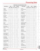
Processing Data PROCESSING RECOMMENDATION GUIDE PCB Vapor Phase Manual Solder Series & Type Wave Solder Vapor Phase Manual Solder Wave Solder Series & Type
Open the catalog to page 10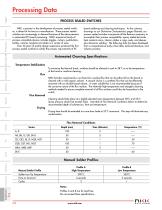
Processing Data PROCESS SEALED SWITCHES NKK, a pioneer in the development of process sealed switches, is ahead of its time as a manufacturer. These process sealed switches are increasingly in demand because of the advancements in automated PC board processing. NKK’s expansive family of process compatible devices includes toggles, rockers, pushbuttons, tactiles, rotaries, keylocks and slides in a variety of sizes. Over 50 years of quality design experience produced the first process sealed switches to satisfy the process requirements of PC board soldering and cleaning techniques. As the cutaway...
Open the catalog to page 11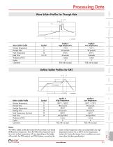
Processing Data Wave Solder Profiles for Through Hole t3 Profile B Low Temperature 110°C 30 seconds 270°C 5 seconds 1.6mm 2 PCB with no Lead Profile A High Temperature 110°C 40 seconds 270°C 6 seconds 1.6mm 2 PCB with no Lead Preheat Temperature Preheat Time Peak Temperature Peak Time Thickness of PCB Cycles Comments Wave Solder Profile Reflow Solder Profiles for SMT 180°C ~ 200°C 120 seconds 230°C 60 seconds 250°C Not Specified 1.6mm 2 PCB with no Lead 150°C ~ 170°C 90 seconds 200°C 30 seconds 240°C Not Specified 1.6mm 2 PCB with no Lead Profile A High Temperature Preheat Temperature Preheat...
Open the catalog to page 12All NKK Switches catalogs and technical brochures
 A Indicators
2 Pages
 Series FT
15 Pages
 KP Series RGB Expansion
8 Pages
 MS series
4 Pages
 SCB-Series
3 Pages
 UB Series
12 Pages
 WB series
4 Pages
 YB series
14 Pages
 YB2
YB213 Pages
 Accessories & Hardware
33 Pages
 Rotaries
46 Pages
 Product Overview
6 Pages
 SmartSwitch
8 Pages
 Illuminated Pushbuttons
116 Pages
 Rockers
118 Pages
 Toggles
119 Pages
 Pushbuttons
130 Pages
 Rockers 2013
16 Pages
 M2 series
7 Pages
 M series
12 Pages
 G series
4 Pages
 D2 series
10 Pages
 BB series
6 Pages
 Switches for Tough Environments
12 Pages
 SMT DIP Rotaries
6 Pages
 Indicators
31 Pages
 Touch Screens
17 Pages
 Tilt Sensors
6 Pages
 Tactiles
47 Pages
 Slides
53 Pages
 Keylocks
23 Pages
 SmartSwitch
48 Pages
 Illuminated Pushbuttons
113 Pages
 Pushbuttons
130 Pages


Archived catalogs
 Tilt Electrical Ratings
1 Page
 SMT Electrical Ratings
1 Page
 Slide Electrical Ratings
1 Page
 Tactile Electrical Ratings
1 Page
 Toggle Electrical Ratings
1 Page


- Single-pole switch
- Push-button switch
- Technology switch
- Multipole switch
- Electromechanical switch
- Rocker switch
- IP67 switch
- Illuminated push-button switch
- Touch push-button switch
- Touch switch
- Action push-button switch
- Form push-button switch
- IP65 push-button switch
- Hermetic switch
- Momentary push-button switch
- Technology push-button switch
- Electromechanical push-button switch
- Metal push-button switch
- Lever switch
- Plastic push-button switch