- Catalogs
- NKK Switches
- Series FT
- Products
- Catalogs
- News & Trends
- Exhibitions
Series FT
1 /15Pages

Series FT
1 /15Pages
Catalog excerpts
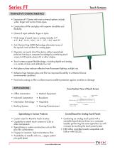
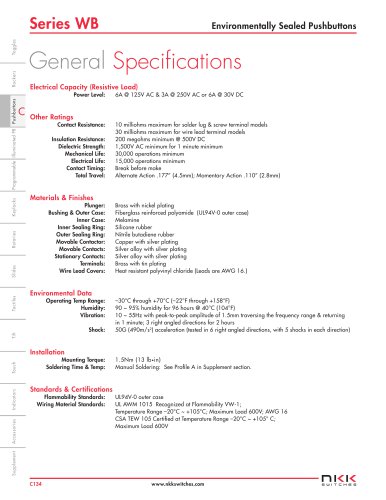
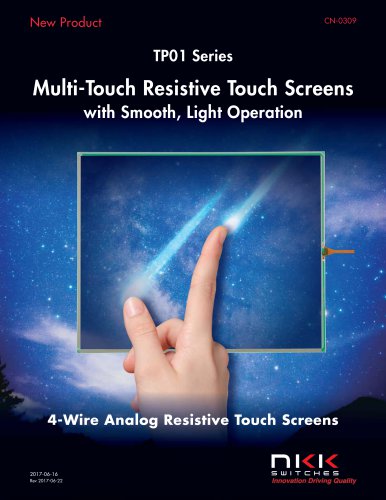
Touch Screens DISTINCTIVE CHARACTERISTICS • Expansion of FT Series with more universal options include wider, larger and narrow frame types • Construction of film and glass with superior durability and flexibility • Choice of input methods: finger or stylus • Wide range of panel sizes in analog includes 5.7”, 6.5”, 8.4”, 10.4”, 10.6", 12.1”, 15”, 15.6” and 19” • Anti-Newton Ring (ANR) Technology eliminates many of the typical visual artifacts for analog types • Operator can easily direct the device without specialized technical training or computer knowledge by combining touch screen to LCD panel, plasma EL or other display • Touch screens support flexible design, including digital and analog, in a variety of sizes and relatively low cost • Anti-glare surface reduces reflection from fluorescent lighting, sunlight, etc. • Adhesive layer between glass and film has improved durability to withstand diverse environmental conditions • Hard resin coating on film's surface ensures excellent protection against scratches or damage Cross Section View of Touch Screen • Office Automation • Medical Equipment • Industrial Automation Transparent Conductive Film Bottom Electrode (Glass or Film) Specializing in Custom Products • • • • • 2 Custom sizes for Resistive Touch Screens Capability to attach touch screens to LCDs or other components Specializing in custom construction such as film plus film combinations Fingerprint resistant, high transmittance films Availability of metallic tails (i.e., copper pattern plus gold plate) www.nkkswitches.com Adhesive Layer • Information Technology • Hospitality • Banking Systems Control Board for Analog Touch Panels • • Combining an analog touch panel with a controller board device driver on a computer enables performing the same operations as with a mouse by touching the touch panel screen NK
Open the catalog to page 1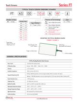
Touch Screens TYPICAL TOUCH SCREEN ORDERING EXAMPLE *Position of Tail (Analog) Screen Size Left or Right (Horizontal) Narrow Frame Type 1 (Horizontal) Narrow Frame Type 2 (Horizontal) Wide Type (Horizontal) Input Method DESCRIPTION FOR TYPICAL ORDERING EXAMPLE * Aspect Ratio: Narrow Frame: 4:3 Wide Frame: 16:9 Touch Screen with 10.6" Screen Wide Type (Horizontal Tail Position) Finger or Stylus Input 4-Wire Analog GENERAL SPECIFICATIONS 4-Wire Analog Resistive Touch Screens Power Level Insulation Impedance Expected Operational Life Writing: 50,000 operations minimum (approximately 30mm movement...
Open the catalog to page 2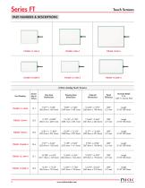
Series FT Touch Screens 4-Wire Analog Touch Screens
Open the catalog to page 3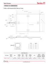
Touch Screens TYPICAL 12.1 DIMENSIONS 4-Wire with Horizontal Tail & Narrow Frame A B Viewable Area C Active Area Center of Active Area Reinforcement Film G Center of Active Area Contact Side Reinforcement Film Bottom Electrode YUP, YLO: Top Electrode Terminal XLE, XRI : Bottom Electrode Terminal Typical Dimensions Part Number Screen Size in Inches Dim G Center of Active Area (Horizontal) Dim H Center of Active Area (Vertical)
Open the catalog to page 4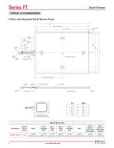
Touch Screens TYPICAL 15.0 DIMENSIONS 4-Wire with Horizontal Tail & Narrow Frame A B Viewable Area C Active Area Center of Active Area Reinforcement Film G Center of Active Area Contact Side Insulated Film Reinforcement Film Bottom Electrode YUP, YLO: Top Electrode Terminal XLE, XRI : Bottom Electrode Terminal Typical Dimensions Part Number Dim G Center of Active Area (Horizontal) Dim H Center of Active Area (Vertical) Screen Size in Inches 15.0
Open the catalog to page 5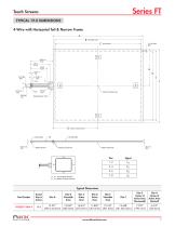
4-Wire with Horizontal Tail & Narrow Frame Contact Side Reinforcement Film Bottom Electrode Pins Signal Typical Dimensions Part Number ni<i< www.nkkswitches.com
Open the catalog to page 6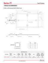
4-Wire with Horizontal Tail & Wide Frame - Contact Side Reinforcement Film Bottom Electrode Pins Signal Typical Dimensions Part Number
Open the catalog to page 7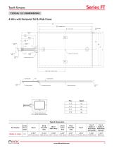
4-Wire with Horizontal Tail & Wide Frame - Contact Side Reinforcement Film Bottom Electrode Pins Signal Typical Dimensions Part Number ni<i< www.nkkswitches.com
Open the catalog to page 8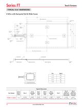
Touch Screens TYPICAL 15.6" DIMENSIONS 4-Wire with Horizontal Tail & Wide Frame A B Viewable Area C Active Area Center of Active Area Reinforcement Film G Center of Active Area Contact Side YUP, YLO: Top Electrode Terminal XLE, XRI : Bottom Electrode Terminal Bottom Electrode Reinforcement Film Typical Dimensions Part Number Screen Size in Inches Dim G Center of Active Area (Horizontal) Dim H Center of Active Area (Vertical)
Open the catalog to page 9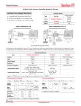
Touch Screens Series FT
Open the catalog to page 10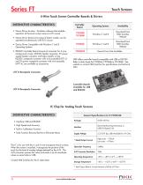
Touch Screens Series FT_ 4-Wire Touch Screen Controller Boards & Drivers “ Operating System Availability • Device Driver function: Emulation software that enables operation of the touch screen same as a PC mouse • Device Driver features two types of button modes; can be operated simultaneously with PS/2 mouse • Device Driver Compatible with Windows 7 and 8 Operating Systems • RS232C Controller Board consists of connector for 4-wire analog touch screen, RS232C header connector, 5V power supply header connector and helps simplify wiring. RS232C receptacle connector with wire assembly (AT713) and...
Open the catalog to page 11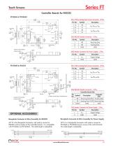
Touch Screens Controller Boards for RS232C FTCS04A & FTCS04A2 (65.0) 2.559 Receiving Data Sending Data CN3 Header Connector for Power Supply - 2 Pins Supply Voltage CN1 4-Wire Analog Touch Screen Connector - 8 Pins (65.0) 2.559 CN2 RS232C Header Connector - 3 Pins Controller Board Side * Pattern on Both Sides is Prohibited Area Direction of Tail Insertion Contact Surface Contact Surface CN2 RS232C Header Connector - 3 Pins Direction of Tail Insertion CN1 4-Wire Analog Touch Screen Connector - 8 Pins (57.0) 2.244 Computer Side Sending Data Sending Data (OUT) Receiving Data CN3 Header Connector...
Open the catalog to page 12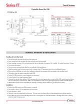
Touch Screens Controller Board for USB * Pattern on Both Sides is Prohibited Area CN4 Header Connector for USB - 5 Pins Contact Surface Direction of Tail Insertion CN1 4-Wire Analog Touch Screen Connector - 8 Pins STORAGE, HANDLING & INSTALLATION Handling of Controller Board • Use arc prevention to protect device from static electricity. • Power source should be activated after host and touch panel are connected. • When inserting connector CN1 and touch panel tail, be sure the slider of connector CN1 is pulled. Do not pull more than 10 times. • Do not alter the product. • Do not use any commands...
Open the catalog to page 13All NKK Switches catalogs and technical brochures
 A Indicators
2 Pages
 KP Series RGB Expansion
8 Pages
 MS series
4 Pages
 SCB-Series
3 Pages
 UB Series
12 Pages
 WB series
4 Pages
 YB series
14 Pages
 YB2
YB213 Pages
 Supplement
33 Pages
 Accessories & Hardware
33 Pages
 Rotaries
46 Pages
 Product Overview
6 Pages
 SmartSwitch
8 Pages
 Illuminated Pushbuttons
116 Pages
 Rockers
118 Pages
 Toggles
119 Pages
 Pushbuttons
130 Pages
 Rockers 2013
16 Pages
 M2 series
7 Pages
 M series
12 Pages
 G series
4 Pages
 D2 series
10 Pages
 BB series
6 Pages
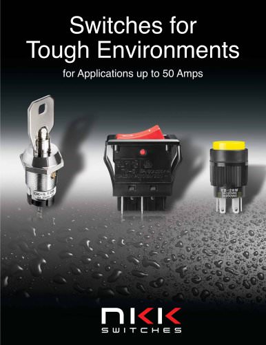 Switches for Tough Environments
12 Pages
 SMT DIP Rotaries
6 Pages
 Indicators
31 Pages
 Touch Screens
17 Pages
 Tilt Sensors
6 Pages
 Tactiles
47 Pages
 Slides
53 Pages
 Keylocks
23 Pages
 SmartSwitch
48 Pages
 Illuminated Pushbuttons
113 Pages
 Pushbuttons
130 Pages


Archived catalogs
 Tilt Electrical Ratings
1 Page
 SMT Electrical Ratings
1 Page
 Slide Electrical Ratings
1 Page
 Tactile Electrical Ratings
1 Page
 Toggle Electrical Ratings
1 Page


- Single-pole switch
- Push-button switch
- Technology switch
- Multipole switch
- Electromechanical switch
- Rocker switch
- IP67 switch
- Illuminated push-button switch
- Touch push-button switch
- Touch switch
- Action push-button switch
- Form push-button switch
- IP65 push-button switch
- Hermetic switch
- Momentary push-button switch
- Technology push-button switch
- Electromechanical push-button switch
- Metal push-button switch
- Lever switch
- Plastic push-button switch