
- Catalogs
- NKK Switches
- Illuminated Pushbuttons

Illuminated Pushbuttons

Illuminated Pushbuttons
This document provides comprehensive specifications and descriptions for various series of illuminated pushbuttons by NKK Switches, focusing on the FP01, GB, and HB series. It highlights their unique characteristics, mechanical and electrical specifications, and recommended applications.
- Illumination: Available in red, green, or amber LEDs, with subdued illumination options.
- Durability: High reliability with a minimum of 3 million operations, using a photo interrupter.
- Construction: Rugged design suitable for environments like gaming and vending machines.
- Mounting: Snap-in mounting with a 6-pin connector socket.
- Size and Weight: Ultra-miniature size for high-density mounting, ideal for handheld equipment.
- Sealing: Totally sealed body construction for contamination prevention.
- Contact Mechanism: STC contact mechanism for smooth actuation.
- LED Options: Single color LED in red, green, or amber.
- Electrical Capacity: Logic level of 0.4VA maximum at 28V AC/DC.
- Durability: Mechanical and electrical life of 50,000 operations minimum.
- Environmental Resistance: Operates in temperatures from -25°C to +55°C.
- Materials: Polyamide construction with gold-plated contacts.
- Electrical Characteristics: Specifications for forward voltage, reverse current, and collector-emitter saturation voltage for various LED colors.
- Mechanical Specifications: Includes total travel, operating force, and temperature range.
- Connector Options: Various connector options available.
- Suitable for low-voltage, low-current, logic-level circuits.
- Recommended for high reliability and contamination resistance environments.
Specifications for subminiature pushbuttons include electrical capacity, materials, environmental data, and installation guidelines. Electrical capacity for resistive loads is specified at a maximum of 0.1A at 30V AC/DC. Contact resistance is capped at 50 milliohms, and insulation resistance is a minimum of 100 megohms at 500V DC. Dielectric strength is 500V AC for at least one minute. Mechanical life is rated at 100,000 operations, with electrical life at 50,000 operations. The nominal operating force is 3.43N, and the contact timing is nonshorting.
The housing and base are made of glass fiber reinforced polyamide. Movable and stationary contacts, as well as terminals, are made of phosphor bronze with silver plating.
The operating temperature range is from -25°C to +50°C for illuminated models and up to +70°C for non-illuminated models. The device can withstand humidity levels of 90-95% for 96 hours at 40°C. It is also tested for vibration and shock resistance.
Maximum mounting torque is 0.49Nm and cap installation force is 9.8N. Soldering guidelines are provided.
The switches are UL recognized when ordered with specific markings. All models are recognized at 0.1A at 30V AC/DC.
Pushbuttons offer full face and spot illumination with various LED color options. They feature a compact design with a latchdown feature for circuit status indication. Dual sliding contacts ensure high reliability and long operating life.
Provides a typical ordering example, detailing the configuration of the switch, including housing color, LED type, and contact materials.
Instructions for cap removal and replacement, LED polarity and orientation, and tools for lamping and mounting are mentioned.
Designed for audio/video applications, featuring quiet actuation and tactile feedback. Offers full face illumination with bicolor LED options and a compact design. Suitable for low-voltage, low-current logic-level circuits.
Detailed specifications for the Series KB Miniature Pushbuttons include electrical capacity for resistive loads, with power levels at 1A @ 125/250V AC or 1A @ 30V DC for silver contacts, and logic levels at 0.4VA maximum @ 28V AC/DC for gold contacts. Contact resistance is capped at 50 milliohms, and insulation resistance is a minimum of 1,000 megohms at 500V DC. Dielectric strength varies between silver and gold contacts, with mechanical life rated at 100,000 operations minimum and electrical life at 50,000 operations for silver and 100,000 for gold.
The housing is made of polyamide (UL94V-0), with movable and stationary contacts made of silver or copper with gold plating, depending on the circuit type. Terminals are made of phosphor bronze or brass with appropriate plating for power or logic level circuits.
The operating temperature range is from -25°C to +50°C for illuminated switches and up to +70°C for non-illuminated ones. The switches can withstand humidity levels of 90-95% for 96 hours at 40°C and vibrations from 10-55Hz with a peak-to-peak amplitude of 1.5mm.
Mounting torque is limited to 0.78Nm, and cap installation force is 4.51N maximum. Soldering guidelines are provided in the supplement section.
The switches meet UL and CSA standards, with specific models recognized at 1A @ 125/250V AC, 1A @ 30V DC, and 0.4VA @ 28V DC.
Pushbuttons offer bright illumination with various color options, including spot illumination. They feature a latchdown mechanism for circuit status indication, snap-action for longevity, and a stainless steel frame to prevent rotation. The body diameter is 12mm, with options for rear panel bushing or snap-in mounting.
Provides a detailed guide on ordering, including options for cap types, colors, and lamp specifications. It also includes information on resistor codes and lamp colors for different voltage requirements.
1. Cutout Dimensions: Various dimensions are provided for switch cutouts, including options with and without barriers.
2. Panel Thickness: Ranges from 0.039” to 0.157” for switches and barriers, and 0.039” to 0.138” for protective guards and splash covers.
3. Electrical Specifications: Voltage options include 5V, 12V, and 110V AC with corresponding current ratings. Endurance is rated at 10,000 hours.
4. Temperature Range: Operating temperature ranges from -25°C to +50°C.
1. Installation: Includes mounting torque specifications and soldering guidelines.
2. Operating Range: Detailed in the supplement section, covering various environmental conditions.
1. Flammability: UL94V-0 standard for housing and base.
2. UL and CSA Certifications: Specific models are recognized and certified under these standards.
1. LED and Lamp Usage: Guidelines for using LEDs and lamps, including voltage and current specifications.
2. Protective Accessories: Recommendations for using protective guards and barriers to enhance durability and safety.
1. Cap Types and Colors: Various cap types and color combinations are available for customization.
2. Optional Accessories: Includes PCB adaptors and protective guards with specific dimensions and materials.
1. LED Specifications: Detailed specifications for different LED colors, including forward current and voltage.
2. Switch Dimensions: Typical dimensions for single and double pole switches are provided.
3. Environmental Data: Includes humidity, vibration, and shock resistance specifications.
The LP01 series features short body pushbuttons with various configurations and specifications. These pushbuttons are designed for use in different applications, offering options for illumination, mounting, and contact materials.
- Contact Ratings: Silver contacts rated at 3A @ 125/250V AC or 30V DC.
- Mounting Types: Available in bushing and snap-in types with specific diameter requirements.
- Housing: Black matte finish, with recommended panel thicknesses for mounting.
- LED Specifications: Red, Amber, and Green LEDs with specific forward and reverse voltage ratings.
- Mounting: Ensure proper spacing between switches when mounted side-by-side.
- Soldering: Wave soldering at 270°C max for 6 seconds or manual soldering at 390°C max for 4 seconds.
- Cleaning: Not process sealed; clean locally with alcohol-based solutions.
- Switches are not UL or cULus marked unless specified. Recognition is only valid when ordered with markings.
The NP01 series offers subminiature pushbuttons with smooth actuation and high reliability, suitable for low-voltage, low-current logic-level circuits.
- Electrical Capacity: 0.4VA max @ 28V AC/DC.
- Contact Resistance: 50 milliohms max.
- Insulation Resistance: 500 megohms min @ 250V DC.
- Mechanical and Electrical Life: 500,000 operations min.
- Materials: Actuator made of silicon rubber, case of polycarbonate resin, and contacts with gold plating.
- Operating Temperature: -25°C to +50°C for illuminated models, -25°C to +70°C for non-illuminated models.
- Available in partitioned trays or stick-tube packaging.
- Optional adaptors and custom legends available.
- Electrical Capacity: Power Level (silver) is 5A @ 125/250V AC or 5A @ 30V DC. Logic Level (gold) is 0.4VA maximum @ 28V AC/DC.
- Contact Resistance: 50 milliohms maximum for silver; 100 milliohms maximum for gold.
- Insulation Resistance: 200 megohms minimum @ 500V DC.
- Dielectric Strength: 1,000V AC minimum between contacts for 1 minute; 1,500V AC minimum between contacts & case for 1 minute.
- Mechanical Life: 1,000,000 operations minimum for momentary; 200,000 operations minimum for alternate action.
- Environmental Data: Operating temperature range is –25°C to +50°C for illuminated and –25°C to +70°C for non-illuminated.
- Housing/Bezel: Glass fiber reinforced polyamide (UL94V-0).
- Snap-in Frame: Stainless steel.
- Movable Contacts: Silver alloy or copper with gold plating.
- Cap Installation Force: 15.0N maximum downward force on cap.
- Soldering: Wave and manual soldering guidelines provided.
- Cleaning: Devices are not process sealed; hand clean using alcohol-based solution.
- Flammability Standards: UL94V-0 housing/bezel & base.
- UL: Recognized only when ordered with marking on switch.
- Wide selection of illumination effects with single and bicolor LEDs.
- Snap-acting contact mechanism provides sensitive actuation with audible feedback.
- Latchdown mechanism offers stability and reliability.
- Bright LED and Super Bright LED specifications are provided, including forward current, voltage, and ambient temperature range.
- Super Bright Bicolor LED specifications include details on forward current and voltage for red/green combinations.
The document outlines the specifications for pushbutton switches, focusing on electrical capacity and logic levels. The power level for silver contacts is rated at 3A for 125/250V AC or 30V DC, while gold contacts are rated at a maximum of 0.4VA at 28V AC/DC.
The switches feature a black housing with a matte finish, and the bezel-barrier is an integral part of the switch body. The materials used include polycarbonate for the lens and insert, and thermoplastic elastomer for seals and filters.
The switches are available in bushing and snap-in mounting types, with options for panel seals. They come with mounting nuts and o-rings for secure installation. The document provides detailed dimensions and panel thickness specifications for proper installation.
The switches support various LED configurations, including spot-illuminated caps with built-in LEDs, bright LEDs, and super bright LEDs. Electrical specifications for LEDs are provided, including forward current, voltage, and ambient temperature ranges. Bicolor LEDs are also available, with specific electrical requirements.
Accessories such as dust/splash covers and protective guards are available to enhance the durability and functionality of the switches. These accessories are made from materials like polycarbonate and glass fiber reinforced polyamide.
The document includes assembly instructions, highlighting the importance of correct LED polarity and orientation. It also mentions available installation tools and provides guidelines for custom legends on switch caps.
The document emphasizes the need for a ballast resistor if the source voltage exceeds the rated voltage for LEDs. It also provides recommendations for printing methods and materials for custom legends.
1. Contact Resistance: Maximum 50 milliohms for silver, 100 milliohms for gold.
2. Insulation Resistance: Minimum 200 megohms at 500V DC.
3. Dielectric Strength: Minimum 1,000V AC between contacts for 1 minute, 1,500V AC between contacts and case for 1 minute.
4. Mechanical Life: 1,000,000 operations minimum for momentary circuit, 200,000 operations minimum for maintained circuit.
5. Electrical Life: 100,000 operations minimum.
6. Nominal Operating Force: 1.5N for single pole, 3.0N for double pole.
7. Contact Timing: Nonshorting (break-before-make).
8. Travel: Pretravel and overtravel of 0.059” (1.5mm), total travel of 0.118” (3.0mm).
1. Bezel: Black glass fiber reinforced polyamide (UL94V-0) or chrome plated over ABS resin (UL94V-2).
2. Housing and Base: Glass fiber reinforced polyamide (UL94V-0).
3. Contacts: Movable contacts made of phosphor bronze with silver or gold plating; stationary contacts of silver alloy or copper with gold plating.
4. Terminals: Phosphor bronze with tin plating.
1. Operating Temperature Range: -25°C to +50°C for illuminated, -25°C to +70°C for non-illuminated.
2. Humidity: 90-95% for 240 hours at 40°C.
3. Vibration: 10-55Hz with 1.5mm amplitude, tested in three directions for 2 hours.
4. Shock: 50G acceleration, tested in six directions.
5. Sealing: IP65 of IEC60529 standard.
1. Mounting Torque: Maximum 0.785Nm (6.95 lb•in).
2. Soldering: Manual soldering as per Profile A in the supplement section.
1. Flammability Standards: UL94V-0 for housing, base, and black bezel.
2. UL Recognition: File No. E44145, recognized with specific markings and ratings.
1. Design: 24mm square and 25mm diameter pushbuttons with splashproof design, meeting IP65 standards.
2. Actuation: Tamper-resistant actuators with a short body design for space conservation.
3. Appearance: Various cap colors and brilliant LED illumination options.
4. Mechanism: Snap-action contact mechanism with arc barrier protection.
5. Customization: Custom legends available on actuators.
1. Bright and Super Bright LEDs: Various forward currents and voltages specified for different colors and configurations.
2. Ballast Resistor Calculation: Provided for LEDs when source voltage exceeds rated voltage.
Specifications and Components:
- The document provides assembly instructions for round and square pushbuttons, specifically for Series YB2 Panel Seal Pushbuttons.
- Key components include the LED, knurled mounting nut, bezel, o-rings, actuator, and housing.
- LEDs are electrostatic sensitive devices, requiring careful handling and installation in an electrostatic protected work station.
- Align the D-flat on the LED with the part number on the switch for correct polarity and insert the LED into the base.
- The larger metal part within the LED represents the cathode (-).
- Ensure proper alignment of the LED for correct polarity.
1. Remove the knurled mounting nut.
2. Remove the bezel and blue o-ring from the housing.
3. Install the LED, ensuring correct polarity alignment.
4. Align tabs on the actuator with projections inside the housing and snap the actuator into place.
5. Reinstall the blue o-ring at the inside bottom of the bezel.
6. Align the tab inside the bezel with the keyway on the housing and reposition the bezel.
7. Ensure the square gasket is present at the back of the bezel before panel installation. Align the keyway on the bezel with the tab in the panel and push the switch into the panel.
8. Attach the mounting nut behind the panel and tighten without overtightening. Maximum mounting torque is 0.785Nm (6.95 lb•in).
- LEDs are sensitive to electrostatic discharge; handle them in a protected environment.
- Use recommended methods such as laser etching, screen printing, or pad printing for legends on caps.
- Epoxy-based ink is recommended for printing.
- NKK Switches offers custom legends for caps upon request.
- Suggested printable areas for film inserts are provided, with specifications for film material and thickness.
This document provides detailed assembly instructions and handling precautions for round and square pushbuttons, emphasizing the importance of correct LED polarity alignment and electrostatic protection.
Catalog excerpts

Contents Toggles Photo Interrupter 3 Million Actuations 6-pin Connector Snap-in Mount Illuminated Pushbuttons Audio/Video Quiet Actuation; 0.4VA Logic Level Bicolor LED PCB Mounting 1A Power Level & 0.4VA Logic Level Full Face & Spot Illumination Solder Lug; Bushing & Snap-in Mount Audio/Video with Silent & Audible Options 100mA Low Level Bicolor LED & Custom RGB Custom Rectangular Cap Assembly & Home Keys PCB Mounting Snap-in Mount 3A Power Level & 0.4VA Logic Level Full Face & Spot Illumination; Super Bright & Bright LEDs Solder Lug/Quick Connect D2
Open the catalog to page 1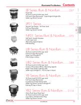
Contents Toggles 3A Power Level & 0.4VA Logic Level Full Face & Spot Illumination Incandescent & Multi-element LEDs Solder Lug/Quick Connect & Straight PC Bushing & Snap-in Mount 22mm Flush Mount Panel Seal 3A Power Level & 0.4VA Logic Level Cap Option with Illumination Ring Solder Lug/Quick Connect www.nkk.com 5A Power Level & 0.4VA Logic Level Variety of Illumination Effects; Alternating Legends Bright, Super Bright, & Bicolor LEDs Solder Lug & Straight PC; PCB & Snap-in Mount 5A Power Level & 0.4VA Logic Level Full Face & Spot Illumination Solder Lug & Straight PC PCB & Snap-in Mount Soft...
Open the catalog to page 2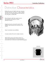
Distinctive Characteristics Brilliant illumination for highly visible status indication with LEDs and caps in red, green, or amber; subdued illumination for low light requirements with white cap over red, green, or amber LEDs. Snap-in mounting for easy installation. Connector socket with 6 pins for simple connection. Rugged construction and smooth actuation allow repeated, rapid actuation force anywhere on cap surface. Photo interrupter, rather than contacts, ensures high reliability and long life of 3 million operations minimum. Contactless Pushbuttons Well suited for gaming and vending machines,...
Open the catalog to page 3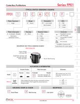
Contactless Pushbuttons TYPICAL SWITCH ORDERING EXAMPLE Photo Transistor (Momentary Operating Function) Actuator Colors Assembled Connector with Wire Leads Unassembled Connector and Pins * Available in Americas only DESCRIPTION FOR TYPICAL ORDERING EXAMPLE Contact factory for custom options Rotaries FP0115CAC1FF Green Actuator with Green LED Single Photo Transistor with Normally Unshaded Photo Interrupter Round, Black Housing ACTUATOR & INTERRUPTER When shaded, the photo transistor momentarily activates electrical function which signals the external device to change its state. HOUSING SHAPE &...
Open the catalog to page 4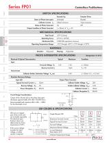
Contactless Pushbuttons SWITCH SPECIFICATIONS Actuator Up Status of Photo Interrupter: Collector Current IC: Status of Photo Transistor: MECHANICAL SPECIFICATIONS Total Travel: Operating Force: Mechanical Life: Operating Temperature Range: MATERIALS Actuator: PHOTO INTERRUPTER SPECIFICATIONS Output Condition of Photo Transistor: Actuator Down Electrical & Optical Characteristics Collector-Emitter Saturation Voltage VCE sat: Forward Voltage VF: Transmission Absolute Maximum Ratings Input LED Output Photo Transistor Typical Forward Current IF: Collector-Emitter Voltage VCEO: Emitter-Collector Voltage...
Open the catalog to page 5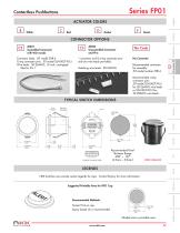
Contactless Pushbuttons ACTUATOR COLORS D Connector body: JST model ZHR-6 Crimp connector pins: JST model SZH-002T-P0.5 Wire leads: 28-26AWG; 12-inch, unstripped; Blue for Pin 1 AT022 Unassembled Connector and Pins 1 connector and 8 crimp connector pins only (no wire leads provided). Matching wire leads: 28-26AWG AT021 Assembled Connector with Wire Leads No Connector Recommended connector for assembly: JST model number ZHR-6 Recommended crimp connector pins: JST model SZH-002T-P0.5 for 28-26AWG wire leads or SZH-003T-P0.5 for 32-28AWG wire leads. TYPICAL SWITCH DIMENSIONS Pin 1 (1.1)R Typ .043...
Open the catalog to page 6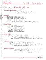
General Specifications Electrical Capacity (Resistive Load) Logic Level: 0.4VA maximum @ 28V AC/DC maximum (Applicable Range 0.1mA ~ 0.1A @ 20mV ~ 28V) Note: Find additional explanation of operating range in Supplement section. Other Ratings Contact Resistance: 80 milliohms maximum Insulation Resistance: 500 megohms minimum @ 500V DC Dielectric Strength: 500V AC minimum for 1 minute minimum Mechanical Life: 50,000 operations minimum Electrical Life: 50,000 operations minimum Nominal Operating Force: 1.70N Travel: Pretravel .035” (0.9mm); Overtravel .008” (0.2mm); Total Travel .043” (1.1mm) Materials...
Open the catalog to page 7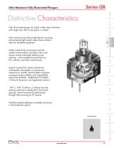
Distinctive Characteristics Fully illuminated plunger for highly visible status indication with single color LED in red, green, or amber. Ultra-miniature size allows high density mounting, and extremely light weight makes these switches ideal for handheld equipment. Totally sealed body construction prevents contact contamination and allows time- and money-saving automated soldering and cleaning. Insert-molded terminals lock out flux, solvents, and other contaminants. Ultra-Miniature Fully Illuminated Plungers Award-winning STC contact mechanism with benefits unavailable in conventional mechanisms:...
Open the catalog to page 8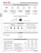
Ultra-Miniature Fully Illuminated Plungers TYPICAL SWITCH ORDERING EXAMPLE Right Angle DESCRIPTION FOR TYPICAL ORDERING EXAMPLE GB15JHF SPDT ON-(ON) Circuit Right Angle PC Terminals Clear Plunger, Green LED POLE & CIRCUIT Plunger Position ( ) = Momentary Connected Terminals Throw & Switch/Lamp Schematics Note: Terminal numbers are not actually on the switch. LED circuit is isolated and requires an external power source. SPDT Clear Plunger LEDs are an integral part of the switch and not available separately. The electrical specifications shown are determined at a basic temperature of 25°C. Maximum...
Open the catalog to page 9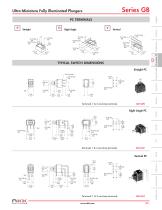
Ultra-Miniature Fully Illuminated Plungers PC TERMINALS TYPICAL SWITCH DIMENSIONS Terminals 1 & 3 are lamp terminals. Terminals 1 & 3 are lamp terminals. GB15JHF Terminals 1 & 3 are lamp terminals. www.nkk.com Right Angle
Open the catalog to page 10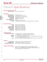
General Specifications Electrical Capacity (Resistive Load) Power Level (silver): Subminiature Pushbuttons Other Ratings Contact Resistance: Insulation Resistance: Dielectric Strength: Mechanical Life: Electrical Life: Nominal Operating Force: Contact Timing: Travel: 50 milliohms maximum 100 megohms minimum @ 500V DC 500V AC minimum for 1 minute minimum 100,000 operations minimum 50,000 operations minimum 3.43N Nonshorting (break before make) Pretravel .087” (2.2mm); Overtravel .031” (0.8mm); Total Travel .118” (3.0mm) Materials & Finishes Housing: Glass fiber reinforced polyamide Base: Glass...
Open the catalog to page 11All NKK Switches catalogs and technical brochures
 A Indicators
2 Pages
 Series FT
15 Pages
 KP Series RGB Expansion
8 Pages
 MS series
4 Pages
 SCB-Series
3 Pages
 UB Series
12 Pages
 WB series
4 Pages
 YB series
14 Pages
 YB2
YB213 Pages
 Supplement
33 Pages
 Accessories & Hardware
33 Pages
 Rotaries
46 Pages
 Product Overview
6 Pages
 SmartSwitch
8 Pages
 Rockers
118 Pages
 Toggles
119 Pages
 Pushbuttons
130 Pages
 Rockers 2013
16 Pages
 M2 series
7 Pages
 M series
12 Pages
 G series
4 Pages
 D2 series
10 Pages
 BB series
6 Pages
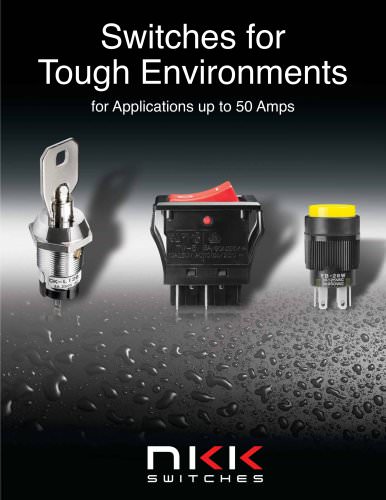 Switches for Tough Environments
12 Pages
 SMT DIP Rotaries
6 Pages
 Indicators
31 Pages
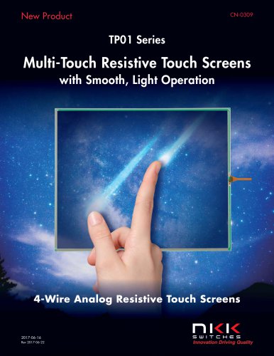
 Touch Screens
17 Pages
 Tilt Sensors
6 Pages
 Tactiles
47 Pages
 Slides
53 Pages
 Keylocks
23 Pages
 SmartSwitch
48 Pages
 Illuminated Pushbuttons
113 Pages
 Pushbuttons
130 Pages


Archived catalogs
 Tilt Electrical Ratings
1 Page
 SMT Electrical Ratings
1 Page
 Slide Electrical Ratings
1 Page
 Tactile Electrical Ratings
1 Page
 Toggle Electrical Ratings
1 Page


- Single-pole switch
- Push-button switch
- Technology switch
- Multipole switch
- Electromechanical switch
- Rocker switch
- IP67 switch
- Illuminated push-button switch
- Touch push-button switch
- Action push-button switch
- Form push-button switch
- Touch switch
- IP65 push-button switch
- Hermetic switch
- Momentary push-button switch
- Technology push-button switch
- Electromechanical push-button switch
- Metal push-button switch
- Plastic push-button switch
- Lever switch