
- Catalogs
- Nippon Gear
- Screw jack ball

Screw jack ball

Screw jack ball
Overview
This document provides comprehensive technical guidelines and specifications for selecting, calculating, and operating screw jacks, focusing primarily on types J2G, J3GH, and the JFB series. It covers selection procedures, key formulas, performance data, dimensional details, operational limits, and additional design considerations to ensure safe and efficient use.
1. Selection Procedure
- Initial Size Selection: Choose a screw jack size based on standard capacity to meet the lifting load.
- Input Shaft Speed Calculation: Assume worm reduction ratio "H" and calculate input shaft speed (rpm) from the lifting speed.
- Torque Calculation: Determine input shaft torque from the lifting load using specified coefficients.
- Manual Operation Consideration: Calculate hand wheel radius if manual operation is intended.
- Power Requirement: Compute required power per jack from torque and rpm.
- Verification: Check against ball screw jack type J-B and consider worm reduction ratio "L" for low speed or fine adjustment needs.
- Limit Checks: Confirm maximum allowable input shaft rpm, power per jack, and buckling load are not exceeded; if exceeded, select a different size.
2. Key Formulas and Parameters
- Input Shaft Speed (n): n = (V / C) × 1000, where V = lifting speed (mm/min), C = speed coefficient (e.g., 1.33).
- Input Shaft Torque (T): T = a × W + b, where W = lifting load (kN), a = torque coefficient (e.g., 0.99), b = no-load torque (e.g., 2 N·m).
- Required Power (P): P = (n × T) / 9550 (kW).
3. Example Calculation
- For a 30 kN load and 1000 mm/min lifting speed:
- Input shaft speed: 751.9 min⁻¹
- Input shaft torque: 31.7 N·m
- Required power: 2.5 kW
- Since J2G max power is 2.3 kW (insufficient), J3GH with 3.1 kW max power is selected.
4. Specifications and Performance Data
- Capacity ranges from 10 to 1000 kN across size numbers J0G to J7A.
- Lifting screw diameters and leads vary by model.
- Worm gear ratios (H and L) and efficiencies are specified.
- Maximum allowable power per jack and input shaft speeds are defined.
- Torque coefficients and no-load torque values are provided.
- Allowable buckling and overhang loads are detailed.
- Approximate weights and grease charging quantities are included.
5. Design and Operational Notes
- Oil lubrication is mandatory for input speeds ≥ 1000 min⁻¹.
- Allowable overhang load is calculated via a specific formula (not detailed).
- Self-locking may fail under impact or vibration; brakes are recommended in such cases.
- Standard service temperature ranges: -15 to +80°C (J0G to JGA), -15 to +100°C (J4A to J7A); custom options available.
- Do not operate jacks outside specified temperature ranges due to unlocked lifting screw ends.
- Special accuracy or grade requirements require consultation.
6. Dimensional Data
- Detailed tables provide stroke lengths, directions, grease fitting locations, hand wheel and shaft dimensions, thread sizes, and depths for various sizes and types.
7. Additional Notes
- Allowable side forces for lifting and suspending jacks are specified.
- Graphs (not included) assist in selecting size numbers based on load and screw speed.
- Prevent key torque and input shaft allowable overhang loads are provided for safety and design.
8. Allowable Buckling Load and Load Capacities (JFB Series)
- Allowable buckling loads range from 0.5 kN to 1000 kN depending on jack size.
- Load capacities increase progressively from J0B to J7B models (17.5 kN to 123.7 kN).
9. Mechanical Properties and Elasticity
- Modulus of longitudinal elasticity: 2.1×10⁵ N/mm².
- Load ratings and mechanical properties are provided for various jack sizes.
10. Stroke and Travel Distance
- Stroke lengths vary from 100 mm to over 500 mm depending on model.
- Expected travel distance is calculated considering stroke, daily cycles, annual usage, and service life for maintenance planning.
11. Dimensional Data and Symbols
- Comprehensive dimensional tables include diameters, lengths, bolt sizes, and mounting dimensions.
- Symbols such as A, AA, L, LH, and T series correspond to specific measurements critical for installation.
12. Operational Limits and Recommendations
- Maximum rotational speed: 1,800 min⁻¹ for high-speed applications.
- Stroke lengths over 500 mm require manufacturer consultation.
- Corrosion resistance options include stainless steel (SUS 304) lifting screws.
- Mounting conditions under compressive loads and lateral load considerations are detailed.
13. Geared Limit Switch Setting Procedure
- Stepwise instructions for setting geared limit switches: cover removal, stopper adjustment, button locking, alignment verification, and operational testing.
14. Braking Torque Calculations
- Formulas and parameters for calculating total braking torque on motor shaft, considering load torque, inertia, gear ratios, and stopping time.
- Essential for selecting appropriate motor and brake systems.
15. Main Specifications of Related Components
- Details on ball screws, racks, and worm gears including diameters, leads, efficiencies, maximum power, and approximate masses.
- Supports component selection matching load and speed requirements.
16. Inquiry Specification Form
- Standardized form for customers to specify load conditions, environment, service frequency, stroke, driving source, and other parameters.
- Facilitates accurate product selection and customization.
17. Manufacturer and Contact Information
Includes Nippon Gear Co., Ltd. contact details for customer support and inquiries.
Critical Information Summary
- Strict adherence to allowable buckling loads and load capacities is essential for safety.
- Stroke length and travel distance calculations are vital for durability and maintenance planning.
- Dimensional data must be reviewed carefully for proper installation.
- Consider high-speed operation limits and corrosion resistance based on application environment.
- Proper geared limit switch setting is crucial for operational safety.
- Braking torque calculations guide motor and brake selection.
- Customer inquiry forms ensure accurate specification and product matching.
Catalog excerpts

Screw Jack Self-locking characteristic: Since it has a self-locking function due to the adoption of trapezoidal thread of an optimum lead, this screw jack does not need any braking mechanism in the driving shaft system. Fixed quantity operating characteristic: This screw jack permits fixed quantity operation because the adoption of high-accuracy worm and screw makes it possible to obtain a lifting screw lead proportionated to the amount of rotation of the input shaft. Anti-backlash type is also available for uses in which hysteresis must be avoided. Interlocking characteristic: Since the input...
Open the catalog to page 2
Common items Screw jack Ball screw jack Selection of jack size No. Basic specifications Lifting load/lifting screw speed graphs Allowable buckling load Allowable side force Drawings of outside dimensions Traveling nut type jack Jack with hand wheel, Jack with motor Bevel gear-type jack Basic specifications Lifting load/lifting screw speed graphs Allowable buckling load Expected traveling distance Drawings of outside dimensions Traveling nut type jack Geared limit switch Setting direction symbols Geared limit switch setting procedure Braking device Jack system Jack with trunnion base Antibacklash...
Open the catalog to page 3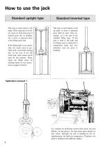
Standard upright type Standard inverted type This type is used mainly to lift loads. If the structure to be lift- ed cannot be held horizontal at joinned parts due to bending, use a clevis or spherical piece If the lifting guide is not detain- able, the screw must be pro- vided with a prevented rotating screw jack, other means can be used for this purpose. Please check the lifting screw for buckling based on the instruc- This type is used mainly to pull up loads. A clevis or spherical piece shall be used, when ne- standard lifting type. If this type is used to lift loads and the lifting screw...
Open the catalog to page 4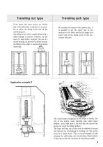
Traveling jack type If the upper and lower spaces are limited and if the full stroke is required, it is possi- ble to rotate the lifting screw and lift the The lifting screw end is usually fitted with a radial bearing to prevent vibration. In the case of a long stroke, however, the use of a thrust bearing can prevent buckling because the lifting screw shaft is subjected to tensile If necessary by reason of the power unit, it is possible to set the screw jack to the structure to be lifted and fix the upper and lower ends of the lifting screw to the sta- tionary structure. The tourist boats navigating...
Open the catalog to page 5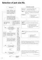
Selection of jack size No. [Calculation example] Specification Required jack performance Select temporarily the size No. of the screw jack having the standard capacity to meet the load. Load at the time of lifting: 30 kN Lifting speed: 1000 mm/min. Select temporarily J2G and obtain the input shaft min-1 “n” assuming the worm reduction ratio as “H”. Formula (1) n Assume the worm reduction ratio as"H"and obtain the required input shaft rpm from the lifting speed. Set the hand wheel radius if the screw jack is to be used for manual operation. If low speed or fine adjustment is specially required,...
Open the catalog to page 6
When you purchase our jack, please order it by product code No. Note (2): If the jack is provided with a geared limit switch or RC encoder, specify the direction of its setting according to the figures on page 26.
Open the catalog to page 7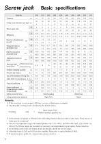
Capacity Lifting screw diameter and lead Maximum allowablepower per jack Worm gear ratio Required input at allowable load Maximum input at allowable load Allowable maximum input (Without prevent key) kg (With prevent key) Grease charging quantity Prevent key torque Input shaft allowable overhang load Input shaft no load torque b Troque coefficient Speed coefficient c (screw lead per rotation of input shaft) Lifting screw forming Roll threading Rigid PVC Lifting screw cover material Machining Steel Remarks: 1) If the screw jack is used at input 1,000 min-1 or over, oil Iubrication is adopted....
Open the catalog to page 8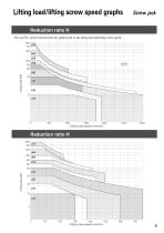
The size No. can be selected from the graph based on the lifting load and lifting screw speed. Lifting screw speed (mm/min) Lifting screw speed (mm/min)
Open the catalog to page 9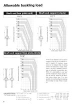
Allowable buckling load Shaft end free (plain end) Shaft support length (mm) A wire 5 mm diameter can be used to suspend a load of one ton without re- gard to length. If, therefore, screw jacks are so designed that the lifting screws are subjected to tensile loads, there is no fear of buckling. This de- sign is preferable economically also. When it is unavoidable to use your jack for compressive loads, please se- lect the size No. based on the allow- able values shown here. It is also possible to avoid buckling by adopting the traveling nut type. Please consult Per = allowable buckling load n...
Open the catalog to page 10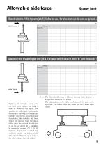
Allowable side force Screw jack Allowable side force of lifting-type screw jack: N (If bellows are used, the values for one size No. above are applicable. side force Suppose, for example, screw jacks are used on a transfer car lifting a load, as shown in this figure. The transfer car will repeat acceleration, deceleration and stop. If the jacks are operated also during acceleration and deceleration, the allowable side force should be checked from the above tables using the value of the side for- however, the jacks are operated only while the transfer car is at rest, the side force is allowable...
Open the catalog to page 11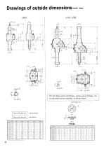
Drawings of outside dimensions — with bellows
Open the catalog to page 12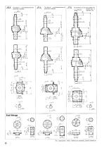
6 A The values in ( ) are dimensions when the JpA The values in ( ) are dimensions when the vj 7 A The dimensions are the same whether the For dimensions when bellows are attached, please consult us.
Open the catalog to page 14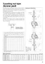
Screw jack An ordinary screw jack requires a space more than double its stroke, as its lifting screw moves up and down. If the space is limited and if the full stroke is required, we recommend this traveling nut type screw jack. Since the lifting screw is rotated and the nut fixed to the object to be lifted travels back and forth on the lifting screw, this screw jack is called the traveling nut type. The lifting screw end is provided with a spherically finished part so that the load can be lifted stably without using any guide even in the case of Although a radial bearing is used to support the...
Open the catalog to page 15All Nippon Gear catalogs and technical brochures
 Gears
Gears2 Pages
 LSB
LSB2 Pages
 Jacks Lineup
8 Pages
 Company Profile
12 Pages
 Valve Actuator Products Guide
16 Pages
 JPQ series
8 Pages
 SMB Series
24 Pages
- Valve
- Pneumatic valve
- Regulating valve
- Pneumatically-operated valve
- Lift valve
- Valve actuator
- Rotary valve actuator
- Electric valve actuator
- Plug valve
- Steel jack
- Double-acting valve actuator
- Straight-toothed gear
- Compact valve actuator
- Manual valve actuator
- Trapezoidal screw jack
- Rack jack
- Multi-turn valve actuator