
- Catalogs
- Ningguo BST Thermal Products Co.,Ltd
- Exhaust Insulation Blanket

- Company
- Products
- Catalogs
- News & Trends
- Exhibitions
Exhaust Insulation Blanket
Exhaust Insulation Blanket
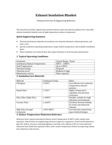
- Thermal performance is influenced by insulation core material, thickness, exhaust geometry, and outer cover.
- Key specifications include continuous operating temperature, target surface temperature, and available installation space.
- Begin by selecting the insulation core material, then adjust thickness to meet thermal requirements.
- Continuous Exhaust Temperature: 500°C – 1000°C
- Peak Temperature: Up to 1200°C
- Thermal Cycling: Frequent
- Vibration Level: Medium to High
- Maintenance Access: Often required
- Fiberglass: Continuous Temp ≤ 550°C; cost-effective for moderate temperature systems.
- Basalt Fiber: Continuous Temp ≤ 750°C; higher temperature capability and abrasion resistance.
- Silica Fiber (High SiO₂): Continuous Temp ≤ 1000°C; flexible and suitable for high vibration environments.
- Ceramic Fiber: Continuous Temp ≤ 1260°C; excellent thermal stability for turbo and industrial exhaust.
- High-Silica Aerogel Composite: Continuous Temp ≤ 650–800°C; low thermal conductivity for space-limited designs.
Based on a typical uninsulated exhaust surface temperature of 600°C. Actual results depend on various factors such as pipe OD, airflow, and fastening tightness. Options with a 0.1 mm embossed aluminum heat shield liner can further reduce outer surface temperature.
| Material | Thickness | Uninsulated Surface | Surface With Blanket |
|---|---|---|---|
| Fiberglass | 6 mm | 600°C | 260–320°C |
| Fiberglass | 10 mm | 600°C | 220–280°C |
| Fiberglass | 20 mm | 600°C | 160–220°C |
| Basalt Fiber | 6 mm | 600°C | 240–300°C |
| Basalt Fiber | 10 mm | 600°C | 200–260°C |
| Basalt Fiber | 20 mm | 600°C | 140–200°C |
| Silica Fiber (High SiO₂) | 6 mm | 600°C | 220–290°C |
| Silica Fiber (High SiO₂) | 10 mm | 600°C | 180–240°C |
| Silica Fiber (High SiO₂) | 20 mm | 600°C | 120–180°C |
| Ceramic Fiber | 6 mm | 600°C | 210–280°C |
| Ceramic Fiber | 10 mm | 600°C | 170–230°C |
| Ceramic Fiber | 20 mm | 600°C | 110–170°C |
| High-Silica Aerogel Composite | 6 mm | 600°C | 190–260°C |
| High-Silica Aerogel Composite | 10 mm | 600°C | 140–200°C |
| High-Silica Aerogel Composite | 20 mm | 600°C | 90–150°C |
| Ceramic Fiber + 0.1 mm Embossed Aluminum Heat Shield (liner) | 10 mm | 600°C | 150–210°C |
| High-Silica Aerogel Composite + 0.1 mm Embossed Aluminum Heat Shield (liner) | 10 mm | 600°C | 120–180°C |
| High-Silica Aerogel Composite + 0.1 mm Embossed Aluminum Heat Shield (liner) | 20 mm | 600°C | 80–130°C |
- Select insulation material based on continuous temperature rather than peak temperature.
- Increase thickness to achieve lower target surface temperature.
- Ceramic or high-silica insulation is recommended for turbochargers.
- Choose outer cover based on abrasion, oil, and environmental exposure.
Catalog excerpts
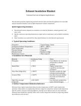
Technical Overview & Engineering Reference This document provides engineering-oriented reference data and selection guidance for removable exhaust insulation blankets used on high-temperature exhaust components. • Thermal performance depends on insulation core material, thickness, exhaust geometry, and outer cover. • Specify continuous operating temperature, target surface temperature, and available installation space. • Select insulation core material first, then adjust thickness to meet thermal requirements. Reference basis: typical uninsulated exhaust surface temperature of 600°C under steady-state operation. Values below are engineering reference ranges for comparison. Actual results depend on pipe OD, airflow, clearance, fastening tightness, and duty cycle. Options with a 0.1 mm embossed aluminum heat shield liner typically reduce outer surface temperature further by improving radiant heat reflection at the hot face.
Open the catalog to page 1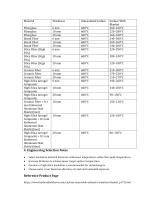
• Select insulation material based on continuous temperature rather than peak temperature. • Increase thickness to achieve lower target surface temperature. • Ceramic or high-silica insulation is recommended for turbochargers. • Choose outer cover based on abrasion, oil, and environmental exposure.
Open the catalog to page 2
Note: Surface temperature ranges shown are typical engineering references. For project specification or compliance, verify by testing under your operating conditions.
Open the catalog to page 3All Ningguo BST Thermal Products Co.,Ltd catalogs and technical brochures
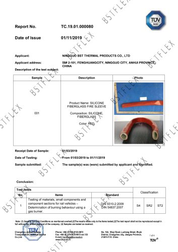 Test Report_DIN54837
1 Page


Archived catalogs
 Fire sleeve reach
1 Page
 Fire sleeve rohs
1 Page
 Woven aramid fabric
1 Page
 BSTFLEX Woven Silica Fabric
2 Pages
 Header Manifold Blanket
1 Page
 Aluminum heat shield
1 Page


