- Catalogs
- NINGBO ZETTLER ELECTRONICS CO., LTD.
- JTV7 AUTOMOTIVE RELAY
JTV7 AUTOMOTIVE RELAY
1 /6Pages

JTV7 AUTOMOTIVE RELAY
1 /6Pages
Catalog excerpts
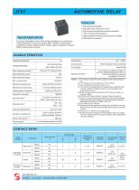
AUTOMOTIVE RELAY Features 70A switching capability Extended temp.range up to 125℃ With transient suppression resistor available 1 Form A contact arrangement Plastic sealed and dust protected types available ROHS & ELV compliant Typical Applications Fog lamp & headlight control, Rear window defogger, Air-conditioning Power distribution, Fuel pump control, ABS, Traction control system, Cooling fan control, Heating control, Power supply management system, Battery disconnection device CHARACTERISTICS Contact arrangement Max.continuous current Max.switching voltage Min.contact load Mechanical endurance Initial insulation resistance Release time 10) Ambient tenperature cover retention (pull&push):200N min terminal retention(pull&push):100N min terminal resistance to bending (front&side):10N min.9) Notes: 1) For 70A type,measured when applying 100% rated votage on coil. 2) For 70A type,see“Load limit curv”for details. 3) 1min.leakage current less than 1 mA. 4) The value is measured when voltage drops suddenly from nominal voltage to 0VDC and coil is not paralleled with suppression circuit. 5) When energized,opening time of NO contacts shall not exceed 100μs. 6) FMVSS 302:Federal Motor Vehicle Safety Standard. 7) Since it is an environmental friendly product,please select lead-free solder when welding.The recommended soldering temperature and time is(250±3),(5±0.3)s. 8) Only valid for QC version. 9) Test point is at 2mm away from teminal end, and after removing testing force, the terminal transfiguration shall not exceed 0.3mm. 10) Only for the 12VDC coil voltage type. 11) Do NOT knock on relays with hard objects such as rubber rod and rubber hammer during mounting, which might lead to relay damage. Electrical endurance Operate time Unit weight Dielectric strength Plastic sealed, Dust protected Voltage drop(initial) CONTACT DATA 4) On/Off ratio Load voltage Load type Load wiring diagram 4) Ambient temp. Contact material Make Break JINTIAN RELAY ISO9001、ISO14001、OHSAS18001 CERTIFIED JINTIAN RELAY
Open the catalog to page 1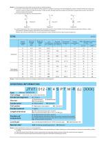
Notes: 1) Corresponds to the peak inrush current on intial actuation. 2) The load in the table excludes flasher.When applied in flasher,a special silver alloy(AgSnO 2)contact material should be used used and the customer special code should be (170)as a suffix.Please heed the anode and cathode’s request when wired, terminal 30 should connect with anode. 3) The load wiring diagrams are listed below: 30 30 + 30 4) Loads mentioned in this chart is for relays with no parellel diode or Zener Diode.For those with parallel diode,Zener Diode or other components, please contact JINTIAN for more technical...
Open the catalog to page 2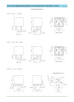
OUTLINE DIMENSIONS,WIRING DIAGRAM AND PC BOARD LAYOUT Unit: JT3FD SUBMINIATURE HIGH POWER RELAYmm Outline Dimensions (Bottom view) (Bottom view) Layout (Bottom view) +0.2 0
Open the catalog to page 3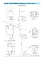
OUTLINE DIMENSIONS,WIRING DIAGRAM AND PC BOARD LAYOUT Unit: JT3FD SUBMINIATURE HIGH POWER RELAYmm Outline Dimensions (Bottom view)
Open the catalog to page 4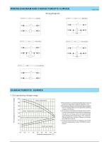
WIRING DIAGRAM AND CHARACTERISTIC CURVES JT3FD SUBMINIATURE HIGH Unit: POWER RELAYmm CHARACTERISTIC CURVES Percentage of nominal coil voltage 1.Coil operaying voltage range 200 Umax. (Standard) 180 1)There should be no contact load applied when maximum continuous operation voltage is applied on coil. 2)The operating voltage is connected with coilpre-energiced time and voltage.After pre-energized,the operating voltage will increase. 3) The maximum allowable coil temperature is 180℃. For the coil temperature rise which is measured by resistance is average value,we recommend the coil temperature...
Open the catalog to page 5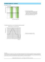
CHARACTERISTIC CURVES 1) The contact load is resistive. 2) The load and electrical endurance tests are made according to “CONTACT DATA”parameters’ table. If actual load voltage,current,operate frequency is different from “CONTACT DATA”table,please arrange corresponding tests for confirmation. 3) This chart takes 70A load as example. 3.Ambient temperature curve of the electrical endurance test Ambient temp. curve (one cycle) Temperature (°C) 1) The minimum temperature is -40℃. 2) The maximum temperature is 125℃. Disclaimer The specification is for reference only. See to “Terminology and Guidelines”for...
Open the catalog to page 6All NINGBO ZETTLER ELECTRONICS CO., LTD. catalogs and technical brochures
 JT102FW SOLAR RELAY
2 Pages
 JTV6 AUTOMOTIVE RELAY
5 Pages
 JT2150W SOLAR RELAY
2 Pages
 JTV4 AUTOMOTIVE RELAY
5 Pages
 JT970 SOLAR RELAY
2 Pages


- Switching relay
- Electromechanical relay
- DC electromechanical relay
- Solid state relay
- Power relay
- Printed circuit board electromechanical relay
- DC solid state relay
- 12VDC electromechanical relay
- 24VDC electromechanical relay
- 48VDC electromechanical relay
- 9VDC electromechanical relay
- 6VDC electromechanical relay
- Printed circuit board solid state relay
- SPST-NO electromechanical relay
- 5VDC electromechanical relay
- 24VDC solid state relay
- High power electromechanical relay
- 1 NC electromechanical relay
- 12VDC solid state relay
- 6VDC solid state relay