- Catalogs
- NINGBO ZETTLER ELECTRONICS CO., LTD.
- JTV6 AUTOMOTIVE RELAY
JTV6 AUTOMOTIVE RELAY
1 /5Pages

JTV6 AUTOMOTIVE RELAY
1 /5Pages
Catalog excerpts
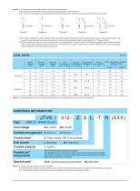
Notes: 1 ) Corresponds to the peak inrush current on intial actuation. 2) Corresponds to the peak inrush current on intial actuation (cold filament). 3) The load wiring diagrams are listed below(The load tests of NC and NO are separated by different samples): 3 4) The load in the table excludes flasher.When applied in flasher,please connect by the polarity request according diagram 3, a special silver alloy contact material should be used and the customer special code should be (170) as a suffix. 5) Loads mentioned in this chart is for relays with no parellel diode or Zener Diode.For those with parallel diode,Zener Diode or other components,please contact JINTIAN for more technical supports. Please also contact JINTIAN if the actual application load is different from what mentioned aboved. COIL DATA Max.allowable overdrive Equivalent Power Coil Parallel Voltage 1) VDC Resistance Resistance resistance consumption Ω W x(1±10%)Ω x(1±5%)Ω at 23℃ at 85℃ Notes: 1) Max.allowable overdrive voltage is stated with no load applied and minimum coil resistance. ORDERING INFORMATION Coil voltage Contact arrangement H:1Form A Construction Coil power Contact material S: Plastic sealed Nil: Dust protected L: Sensitive Parallel coil components R: Parallel transient supression resistors D: Parallel transient supression diode,with anode connected to terminal#2 D1: Parallel transient supression diode,with anode connected to terminal#1 Nill: Without parallel components XXX: Customer special requirement Notes: 1) Dust protected version is recommended. 2) If parallel diode, Zener Diode or other components are required,please contact Jintian for more technical supports. 3) The customer special requirement express as s
Open the catalog to page 1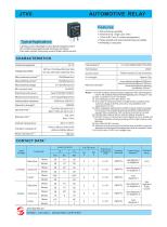
AUTOMOTIVE RELAY Features 30A switching capability Ambient temp. range up to 125℃ 1 Form A &1 Form C contact arrangement Plastic sealed and dust protected types available ROHS&ELV compliant Typical Applications Lighting control,Headlight control,Electromagnet control Air-conditioning,Heaters(seat,front/rear windows), Fan motor control,Fuel pump control,Wiper motors control CHARACTERISTICS Contact arrangement Max.continuous current Max.switching current Plastic sealed, Dust protected Unit weight Max.switching voltage Min.contact load Mechanical endurance Initial insulation resistance Dielectric...
Open the catalog to page 2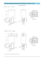
OUTLINE DIMENSIONS,WIRING DIAGRAM AND PC BOARD LAYOUT Unit: JT3FD SUBMINIATURE HIGH POWER RELAYmm Outline Dimensions JTV6/□□□Z□□-□□(XXX) (Bottom view)
Open the catalog to page 3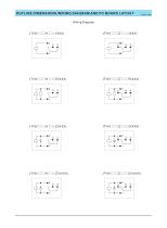
OUTLINE DIMENSIONS,WIRING DIAGRAM AND PC BOARD LAYOUT Unit: JT3FD SUBMINIATURE HIGH POWER RELAYmm Wiring Diagram
Open the catalog to page 4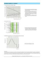
CHARACTERISTIC CURVES 1.Coil operaying voltage range Percentage of nominal coil voltage 1) The operating voltage is connected with coilpre-energiced time and voltage.After pre-energized,the operating voltage will increase. 2) The maximum allowable coil temperature is 180℃. For the coil temperature rise which is measured by resistance is average value,we recommend the coil temperature should be below 170℃ under the different application ambient, different coil voltage and different load etc. 3) If the actual operating coil voltage is out of the specified range,please contact JINTIAN for futher...
Open the catalog to page 5All NINGBO ZETTLER ELECTRONICS CO., LTD. catalogs and technical brochures
 JT102FW SOLAR RELAY
2 Pages
 JT2150W SOLAR RELAY
2 Pages
 JTV7 AUTOMOTIVE RELAY
6 Pages
 JTV4 AUTOMOTIVE RELAY
5 Pages
 JT970 SOLAR RELAY
2 Pages


- Switching relay
- Electromechanical relay
- DC electromechanical relay
- Solid state relay
- Power relay
- Printed circuit board electromechanical relay
- DC solid state relay
- 12VDC electromechanical relay
- 24VDC electromechanical relay
- 48VDC electromechanical relay
- 9VDC electromechanical relay
- 6VDC electromechanical relay
- Printed circuit board solid state relay
- SPST-NO electromechanical relay
- 5VDC electromechanical relay
- 24VDC solid state relay
- High power electromechanical relay
- 1 NC electromechanical relay
- 12VDC solid state relay
- 6VDC solid state relay