- Catalogs
- NINGBO ZETTLER ELECTRONICS CO., LTD.
- JT94F SUBMINIATURE HIGH POWER RELAY
JT94F SUBMINIATURE HIGH POWER RELAY
1 /3Pages

JT94F SUBMINIATURE HIGH POWER RELAY
1 /3Pages
Catalog excerpts
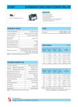
SUBMINIATURE HIGH POWER RELAY Features 25A switching capability Various terminal types Various of mounting position Dust protected type Environmental friendly product (RoHS compliant) Outline Dimensions:(47.0 x 32.0 x 28.5)mm UL insulation system:Class F File No:E319069(AC type only) CONTACT DATA Contact arrangement Contact resistance DC type: Approx. 2.4W; AC type: Approx. 4.0VA Coil power Contact material Contact rating (Res.load) Max.switching voltage Max.switching current Max.switching power COIL DATA Mechanical endurance 5 x 10⁴ ops (25A 277VAC, Resistive load, AgSnO 2,AgCdO,at 65℃,1s on 9s off) 3 x 10⁴ ops(3A 277VAC, General load, AgCe,at 65℃,1s on 9s off) Notes: 1)The data shown above are intial values. Electrical endurance Insulation resistance Between coil&contacts Between open contacts Dielectirc strength Operate time(at nomi.volt.) Release time(at nomi.volt.) Temperature rise(at nomi.volt.) Shock resistance( Functional ) Vibration resistance Ambient tenperature Termination Unit weight Construction Dust protected Notes: 1)The data shown above are intial values. JINTIAN RELAY ISO9001、ISO14001、OHSAS18001 CERTIFIED Notes: 1)The data shown above are intial values. 2)*Maximum Voltage refers
Open the catalog to page 1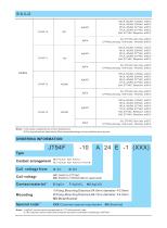
安全认证 ORDERING INFORMATION JT3FD SUBMINIATURE 3A, 277VAC, Gen Use at 65℃ 277VAC pilot duty, 10A inrush, 1A break at 65℃ AgCdO NO/NC 3A, 277VAC, Gen Use at 65℃ 277VAC pilot duty, 10A inrush, 1A break at 65℃ 3A, 277VAC, Gen Use at 65℃ 277VAC pilot duty, 10A inrush, 1A break at 65℃ 3A, 277VAC, Gen Use at 65℃ 277VAC pilot duty, 10A inrush, 1A break at 65℃ Notes: 1) All values unspecified are at room temperature. 2) Only typical loads are listed above.Other load specificationgs can be avaliable upon request. ORDERING INFORMATION JT3FD SUBMINIATURE HIGH POWER RELAY Type Contact arrangement 10:1 Form...
Open the catalog to page 2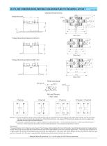
OUTLINE DIMENSIONS,WIRING DIAGRAM AND PC BOARD LAYOUT Unit: JT3FD SUBMINIATURE HIGH POWER RELAYmm Outline Dimensions 2-Ø4.3 Metal Bracket Flang, Mounting Distance 54.8mm 2-Ø3.8 32 Flang, Mounting Distance 66.7mm Wiring Digram (Top view) 1 Form A Remark: 1) The pin dimension of the product outline drawing is the size before tinning (it will become larger after tinning), and the mounting hole size is the recommended design size of the PCB board hole. The specific PCB board hole design size can be mapped and adjusted according to the actual producet. 2) In case of no tolerance shown in outline dimension:outline...
Open the catalog to page 3All NINGBO ZETTLER ELECTRONICS CO., LTD. catalogs and technical brochures
 JT102FW SOLAR RELAY
2 Pages
 JTV6 AUTOMOTIVE RELAY
5 Pages
 JT2150W SOLAR RELAY
2 Pages
 JTV7 AUTOMOTIVE RELAY
6 Pages
 JTV4 AUTOMOTIVE RELAY
5 Pages
 JT970 SOLAR RELAY
2 Pages


- Switching relay
- Electromechanical relay
- DC electromechanical relay
- Solid state relay
- Printed circuit board electromechanical relay
- DC solid state relay
- 12VDC electromechanical relay
- 24VDC electromechanical relay
- 48VDC electromechanical relay
- 9VDC electromechanical relay
- 6VDC electromechanical relay
- Printed circuit board solid state relay
- SPST-NO electromechanical relay
- 5VDC electromechanical relay
- 24VDC solid state relay
- High power electromechanical relay
- 1 NC electromechanical relay
- 12VDC solid state relay
- 6VDC solid state relay