- Catalogs
- NIHON PISCO CO., Ltd.
- VUS-32. SEU-32 Series
- Company
- Products
- Catalogs
- News & Trends
- Exhibitions
VUS-32. SEU-32 Series
1 /1Page

VUS-32. SEU-32 Series
1 /1Page
Catalog excerpts
G. INITIAL SETTING MODE B. OUTPUT CIRCUIT WIRING DIAGRAMS For your safety, please read the following before using. Analog output (Orange) Setting pressure range Withstand pressure Output Specifications Output short circuit protection Response time setting button to select response time. Display color setting ON:Green ON:Red OFF:Red OFF:Green Output Voltage: 1 to 5V ±2.5% F.S. (within rated pressure range) Linearity: ±1% F.S. Output impedance: about 1kΩ Panel adapter ON/OFF: Green button to set display color. Panel adapter Panel adapter Panel adapter Operation: 0 ~ 50°C, Storage:-10 ~ 60°C (No condensation or freezing) Ambient temp. range Unit setting (kPa/MPa) (kgf/cm 2 ) (*2 ) Ambient humidity range Panel Mounting Front protective lid ±2% F.S. ±1 digit (ambient temperature: 25 ±3°C) ACPG-32-B12Mounting bracket ACPG-32-B13Mounting bracket ACPG-31-P1Panel adapter ACPG-31-P2Panel adapter + Front protective lid Two color(Red/Green) main & unit display, Orange sub-display (Sampling rate: 5 times/1sec.) Optional Parts Indicator accuracy V2 Output + 1 Analog output(15V) 22 Output + Copy Function Window comparator mode NNPN Output PPNP Output Output Specifications Response time Hysteresis mode Window comparator mode button to set OUT2 operating mode. PNP: open collector 2 outputs Max. load current: 125mA Max. supply voltage: 24V DC Residual voltage: ≦ 1.5V Hysteresis mode Pressure Range Analog output (Voltage Output) Repeatability(Switch output) OUT 2 Operating mode setting NPN: open collector 2 outputs Max. load current: 125mA Max. supply voltage: 30V DC Residual voltage: ≦ 1.5V Current consumption button to set OUT1 operating mode. Power supply voltage Copy function F. OPTIONAL PARTS DIMENSIONS Window comparator mode Hysteresis mode Filtered air, Non-corrosive / Non-flammable gas Switch output Copy function (Orange) Main circuit OUT 1 Operating mode setting Main circuit Analog output Press SET button for more than 3 seconds. Rated pressure range Main circuit Main circuit Measure mode Do not use corrosive or flammable gas or liquid with this product. Please use within the rating pressure range. Do not apply pressure beyond recommended maximum withstand pressure, permanent damage to the pressure sensor may occur. Do not drop, hit or allow excessive shock. Even if switch body appears undamaged, internal components may be broken and can cause malfunction. Turn power off before connecting wiring. Wrong wiring or short circuit will damage and / or cause malfunction. Do not use in environment containing steam or oil vapor. This product is not explosion-proof rated. Do not use in atmosphere containing flammable or explosive gases. Wiring for pressure sensor should avoid power source line and high voltage line. If use in the same circuit, noise may cause malfunction. Withstand voltage 1000V AC in 1-min (between case and lead wire) button to set desired pressure unit. 50M (at 500V DC, between case and lead wire) Insulation resistance Vibration Total amplitude 1.5mm or 10G,10Hz-55Hz-10Hz scan for 1 minute, two hours each direction of X, Y and Z 100m/s (10G), 3 times each in direction of X, Y and Z Temperature characteristic Lock Indicator ±2.5% F.S. of detected pressure (25°C) at temp. Range of 0~50°C Port size Lead wire 2 Color Main Display Setting Mode Sub-display Section Measure mode Front protective lid Approx. 80g (with 2 meter lead wire) *1.Hysteresis value is adjustable within 1 ~ 8 digits for one point set mode and window comparator mode. *2.Pressure unit switching feature is disabled at the factory. Setting steps for the function active. 1) Turn on pressing “set” and “down” key. 2) Press “down” key → display “on”. 3) Press “set” key. J. PRESSURE SETTING MODE H. ADVANCE SETTING MODE Press SET button for more than 5 seconds. OUT 1mode setting " " (One point set mode) OUT 2mode setting " " (One point set mode) Measure mode Measure mode Mutually display Fixed hysteresis value selection ◎ Copy function setting can use the master sensor to copy the pressure value to the slave Normal open mode Normal close mode Vacuum (VUS-32) 【NOTE:】 *1. This setting mode will not display when output 2 is set to oFF. *2. Pressure unit is MPa by positive & pressure unit is kPa by vacuum and compound *3. Only applicable for Vacuum/ Compound . P. COPY FUNCTION SETTING OUT 1mode setting " " (One point set mode) OUT 2mode setting " " (Not used) Measure mode ◎ Before copying, please confirm the model of pressure sensor. The function cannot use in difference mode. ◎ The copy function only can be one-to-one. 【SETTING STEP】 Mutually display Positive Pressure Positive Pressure Vacuum Pressure 1. Please set the copy function to or to be on copy condition by master sensor. Please refer the copy setting of (H) advance setting mode. 2. Turn power off by slave sensor. 3. Refer the connection way with the master and slaver sensor as followings. MASTER SENSOR SLAVER SENSOR DC(+) (Brown) Normal open mode button to adjust fixed hysteresis value. Mutually display *Hysteresis mode does not have this setting selection. Please refer the item "J" and "K" in detailed. ◎ Setting Condition 3 button to select LCD display color relation button to turn Power-Save mode on or off. Copy Function Setting Mutually display Mutually display Mutually display Positive Pressure display reciprocal the slaver sensor display (mutually display) 6. When convey the data is fail, display reciprocal (Master) sensor displays (Slaver) sensor displays 7.Turn off power and remove the wire connection. If no remove the wire connection, the sensor would be broken. ★If require to copy another slave sensor, please repeat the step 3 to 5 . ★Only for copy function type has this setting selection.. Positive Pressure Vacuum Pressure Positive Pressure Vacuum Pressure *1. If turn on power is not synchronization, the data cannot be copied. *2. When the data conveys fail, please confirm the wire connection. Then repeat the step 3 to 5 . 【NOTE:】 *1. In case hysteresis is set at less than or equal to 2 digits, switch output may chatter if input pressure fluctuates near the set point. *2. When using window comparator mode, the difference between two set points must be greater than the fixed hysteresis, otherwise will cause the switch output to malfunction. How to cancel the copy mode by master sensor: ◎ When the master sensor display Please display reciprocal (display reciprocal), button to leave the copy mode. Q. FINE ADJUSTMENT MODE Analog output range 1-5V, proportional to the pressure range. This function eliminates slight differences in the output values and allows uniformity in the numbers displayed. Displayed values of the pressure sensor can be calibrated to within ±2.5% R.D. Display fine adjustment mode ( Compound ) Analog output(V) Press settings. button to select to restore to default factory Press or adjustment mode. OUT 1mode setting " " (Hysteresis mode) " " (Window comparator mode) OUT 2mode setting " " (One point set mode) Display fine adjustment mode Normal close mode L. ANALOG OUTPUT DESCRIPTION Restore factory setting display reciprocal the master sensor display (mutually display) *OnL : When finishing copy, the slave sensor would be locked automatically. *Only for copy function type has this setting selection. Copy Function (Orange) Measure mode Positive Pressure OUT 1mode setting (3) Window comparator mode: " " (Hysteresis mode) Normal open mode " " (Window comparator mode) Vacuum Positive/Compound OUT 2mode setting (VUS-32) (SEU-32/VUS-32R) " " (Not used) Mutually display OUT 1mode setting " " (One point set mode) OUT 2mode setting " " ( Hysteresis mode ) " " (Window comparator mode) Measure mode Power-Save Mode Press Copy Function (Orange) 5. Wait 5 sec., when finishing to convey the data, Display color selection 4. Turn on power at the same time by master and slaver sensor.(* 1) Displayed pressure value * Applicable for one point set mode and window comparator mode. Normal close mode Mutually display ( Positive ) Analog output(V) ( Vacuum ) Analog output(V) 5 Use or button to change the set value. Press SET button to exit . OUT 1mode setting " " (Hysteresis mode) " " (Window comparator mode) OUT 2mode setting " " (Hysteresis mode) " " (Window comparator mode) Applied pressure :Factory setting display value set prior to shipment :Display calibration range Measure mode R.D. (Real Detect) 【NOTE :】1. setting resolution is ±0.1% R.D. 2. The signal would be changed with analog output after adjusting. button to select to display fine Measure mode Measure mode Measure mode Mutually display N. PEAK/BOTTOM HOLD FUNCTION the same time until the "00" is shown. Release the button to end zero setting. 【NOTE :】 *1. When setting is “ ”, the power-save mode would be started. Please refer the item “ I ” in detailed. *2. When setting " “or " “, the display copy function mode would be started. Please refer the item “ P ” in detailed. *3. When setting is “ ”, the display fine adjustment mode would be started. Please refer the item “ Q ” in detailed. M. ZERO POINT SETTING Press the Mutually display Error Type Press SET + button for more than 2 seconds. Mutually display Measure mode Mutually display pressed after 30 seconds. ◎ During Power-Save mode, the output LCD may not be synchronize with the output. It is normal and will not affect output operation. PE-:Peak Value bo-:Bottom Value Mutually display Measure mode Mutually display Press + SET button for more than 2 seconds. ◎ Use key lock mode to prevent unauthorized or accidental tampering with the switch setting. ◎ When lock mode is selected, panel will display " ". Measure mode Power-Save mode (Main display is off, sub-display will flash " Unlock mode 【NOTE】 Do not disconnect power when the sub-display and setting value is flashing alternately; otherwise the system cannot store the values. ") We reserve the right to change the specification without prior notice. Internal system error Internal system error System error Internal data error Internal data error Copy data error ◎ Press any button to turn-on main display temporarily. During zero reset, ambient pressure is over ±3% F.S. Turn power off and check the cause of overload current or lower the current load under 125 mA, then restart. Change input pressure to ambient pressure and perform zero reset again. Adjust the pressure within operating pressure range. Turn power off, and then restart. If error condition remains, please return to factory for inspection. Please check the model no. and wire connection. Restart to turn on power if no return to normal condition, please return to factory for inspection. No button operation for 30 seconds Output 2 load current is more than 125 mA Supply pressure is exceeds the upper limit of pressure setting. Supply pressure is exceeds the lower limit of pressure setting. Applied pressure error Error Condition Output 1 load current is more than 125 mA I. POWER-SAVE MODE ◎ During Power-Save mode, the main display will turned off if no buttons is Error code Excess load out1 current error out2 Residual pressure error Mutually display R. ERROR CODE INSTRUCTION Lock mode S. PRESSURE UNIT CONVERSION TABLE From
Open the catalog to page 1All NIHON PISCO CO., Ltd. catalogs and technical brochures
 Vacuum Pad for Eggs
6 Pages
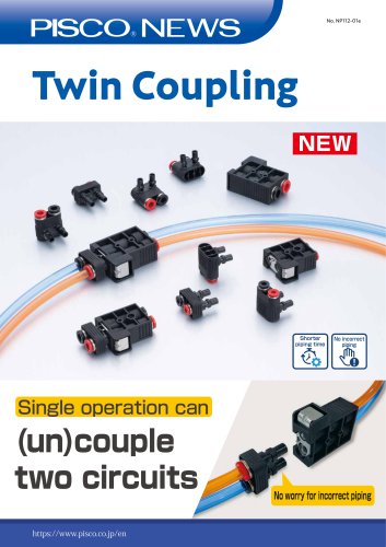 Twin Coupling
6 Pages
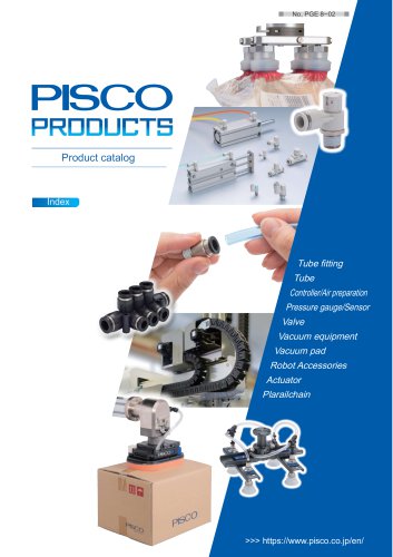 General Product Guide
917 Pages
 CTB series
1 Page
 FUS8 series
3 Pages
 31 & 32 Series
20 Pages
 Vacuum Pad Soft Series
86 Pages
 VP series
106 Pages
 CHA series
8 Pages
 Gripper Series
15 Pages
 SVB Series
50 Pages
 SVA series
13 Pages
 SVR series
31 Pages
 NSB series
8 Pages
 Ball Valve SUS304 series
8 Pages
 BV series
8 Pages
 HV series
5 Pages
 Cable clamp & Dividing sheet
8 Pages
 Plarailchain SC
15 Pages
 Plarailchain SPO
12 Pages
 Plarailchain SP
14 Pages
 HPO
HPO12 Pages
 HPU
HPU12 Pages
 PJN series
15 Pages
 KJNC series
15 Pages
 SSJS series
6 Pages
 Flow Control Valve PP Series
12 Pages
 Stainless SUS316
13 Pages
 UE series
12 Pages
 FB series
1 Page
 CTA series
1 Page
 SFTN series
2 Pages
 SET series
1 Page
 SFT series
14 Pages
 ULF series
12 Pages
 UCQ series
2 Pages
 UQ series
12 Pages
 NB series
12 Pages
 NA series
12 Pages
 UD series
12 Pages
 UBS series
12 Pages
 UBT series
12 Pages
 UC series
1 Page
 UB series
12 Pages
 AK/AS series
26 Pages
 NK series
18 Pages
 Brass Series
30 Pages
 V-0 series
27 Pages
 EG Series
27 Pages
 PP Fitting series
12 Pages
 PP Series
26 Pages
 AP series
18 Pages
 SL series
16 Pages
 P-SUS series
33 Pages
 NS series
24 Pages
 SSP series
8 Pages
 ATS series
6 Pages
 Air Filter
20 Pages
 Combination Unit Series
25 Pages
 SFU series
9 Pages
 JP series
15 Pages
 ET series
11 Pages
 EQ series
19 Pages
 CVLU series
21 Pages
 CV series
24 Pages
 JN series
25 Pages
 Speed Controller Constant Flow
15 Pages
 JSD series
10 Pages
 JS Low-Flow series
17 Pages
 JSC series
13 Pages
 JS series
30 Pages
 Miniature Pressure Regulator
12 Pages
 MA series
16 Pages
 RH series
16 Pages
 R series
16 Pages
 PS series
16 Pages
 L series
41 Pages
 FUS20
FUS207 Pages
 Small Flow Sensor FUS8 Sries
3 Pages
 GP series
13 Pages
 Small Pressure Sensor 11-series
24 Pages
 VUS12 series
2 Pages
 VUS21 series
14 Pages
 VUS8-S series
22 Pages
 JSD series
10 Pages
 Orifice Fitting Series
6 Pages
 JK series
10 Pages
 RVFUP series
6 Pages
 VLF series
16 Pages
 VFL series
8 Pages
 VF series
22 Pages
 ECV series
8 Pages
 VPLFC, VPLFD series
17 Pages
 VPKE series
4 Pages
 RPV06 Series
8 Pages
 VZ Series
34 Pages
 VX Series
42 Pages
 VQ Series
4 Pages
 VN Series
40 Pages
 VK series
53 Pages
 VJ Series
34 Pages
 VG series
21 Pages
 VRL series
17 Pages
 VVV series
11 Pages
 VLS series
4 Pages
 VM | VC series
28 Pages
 VY series
24 Pages
 VB series
11 Pages
 VH | VS series
28 Pages
 VPHMP series
12 Pages
 VYR series
5 Pages
 HS series
13 Pages
 HML series
14 Pages
 VRG series
18 Pages
 Dry Unit Series
33 Pages
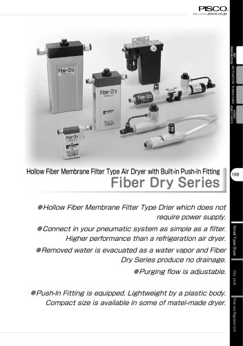
 Fiber Membrane Air Dryer
12 Pages
 VLM series
12 Pages
 VSPE series
5 Pages
 VT series
21 Pages
 PB series
13 Pages
 JSG series
17 Pages
 pararel
3 Pages
 fitting
4 Pages
 BJSU series
4 Pages
 SC
SC15 Pages
 SPO
SPO12 Pages
 SP
SP13 Pages
 RPV pump
8 Pages
 Pre-set
6 Pages
 Stainless Steel Ball Valve
8 Pages
 SUS316 Flow Control Valve
6 Pages
 Flange
13 Pages
 HML
HML14 Pages
 End of Arm Vacuum Gripper
12 Pages
 VYR
VYR5 Pages
 EOAT VRG | VMG series
18 Pages
 VPLFC
VPLFC17 Pages
 SVB
SVB172 Pages
 SVR
SVR39 Pages
 8mm Sensor
22 Pages
 Vacuum Filter
28 Pages
 Fall Prevention
18 Pages
 Vacuum Pen
21 Pages
 Push-Rod Release
4 Pages
 cylinder
22 Pages
 FDAbellows
6 Pages
 Oval
Oval80 Pages
 sponge
50 Pages
 mark-free
34 Pages
 flat
flat42 Pages
 Ultrathin
34 Pages
 packaging bag
13 Pages
 multi-bellow
46 Pages
 bellows pad
74 Pages
 Skid proof pad
42 Pages
 soft bellow pad
60 Pages
 soft pad
66 Pages
 VRL
VRL17 Pages
 VH VS VC VUM VU VY VB
336 Pages
 VZ
VZ34 Pages
 VX
VX42 Pages
 VVV
VVV11 Pages
 VQ
VQ42 Pages
 VN
VN40 Pages
 VLS
VLS4 Pages
 VLM
VLM12 Pages
 VK
VK53 Pages
 VJ
VJ34 Pages
 VG
VG21 Pages
 Vacuum Tube
12 Pages
 Twin Coiling
12 Pages
 Tube Cutter
12 Pages
 Polyurethane Tube
12 Pages
 Nylon Tube Series
12 Pages
 Multi-core Planar Tube
12 Pages
 Low-Friction Polyurethane Tube
12 Pages
 Insert Ring
12 Pages
 Fluororesin (PFA) Tube
14 Pages
 UL series
12 Pages
 Anti-spatter Tube
12 Pages
 Tube Fitting PP Series
26 Pages
 Tube Fitting Mini Series
41 Pages
 Tube Fitting Chemical Series
18 Pages
 K series
30 Pages
 Stop Fitting Series
16 Pages
 Rotary Joint Series
16 Pages
 Multi-Circuit Rotary Block
12 Pages
 Minimal Fitting Series
20 Pages
 Main Block Series
24 Pages
 Light Coupling Series
24 Pages
 High Rotary Joint Series
16 Pages
 Connector Series
16 Pages
 Color Cap
12 Pages
 Brass Compression Fitting Series
18 Pages
 2-Circuit Junction Block Series
16 Pages
 Vacuum EOAT Kit HML
14 Pages
 Vacduum gripper
18 Pages
 Mounting Flange for EOAT.pdf
13 Pages
 SSNC series
13 Pages
 SJSC series
24 Pages
 Speed Controller Series
32 Pages
 Speed Controller PP Series
17 Pages
 Speed Controller Low Flow
17 Pages
 Speed Controller High Flow
13 Pages
 Speed Controller Brass Series
15 Pages
 KJSC series
17 Pages
 Silencer Series
13 Pages
 Quick Exhaust Valve Series
19 Pages
 Pressure Gauge Series
13 Pages
 Miniture quick-exhaust
17 Pages
 Fixed Orifice Joint Series
22 Pages
 Check Valve
4 Pages
 SUS304_Ball Valve Series
8 Pages
 Parallel Gripper
6 Pages
 JSG
JSG17 Pages
 GENERAL
106 Pages
 Mechanical Valve Series
19 Pages
 Ball Valve Series
19 Pages
 Stainless Steel ball valve
6 Pages
 Hand Valve Series
15 Pages
 Change Valve
11 Pages
 SVA21 Series
21 Pages
 P Series
71 Pages
 SVA20 Series
43 Pages
 RegulatorPL031821m
12 Pages
 BJSU series
6 Pages
 NP68-01e
17 Pages