 Website:
NIHON PISCO CO., Ltd.
Group: 株式会社日本ピスコ
Catalog excerpts
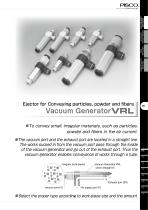
VACUUM EXTERNAL VACUUM GENERATOR CONTROLLER VACUUM PAD VACUUM ACCESSORIES Ejector for Conveying particles, powder and fibers Vacuum GeneratorVRL convey small, irregular materials, such as particles, powder and fibers in the air current. vacuum port and the exhaust port are located in a straight line. The works sucked in from the vacuum port pass through the inside of the vacuum generator and go out of the exhaust port. Thus the vacuum generator enables conveyance of works through a tube. Irregular work-pieces Vacuum Generator VRL (Union Straight A) Exhaust port (EX) Vacuum port (V) the proper type according to work-piece size and the amount.
Open the catalog to page 1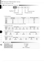
Vacuum Generator Series VACUUM GENERATOR Vacuum Generator VRL ■ Model Designation (Example) VRL ④ Exhaust port size ③ Air supply port size Ring Blow Type ② Vacuum port size ① Performance Final vacuum (-kPa) 53 53 53 53 ※ The performance is based on the value at an air supply pressure 0.5MPa. ② Vacuum port size Joint type Code Size ③ Air supply port size Joint type Code Size ④ Exhaust port size Joint type Code Size Taper pipe thread 02 R1/4 ■ Specification Fluid medium Operating pressure range Rated supply pressure
Open the catalog to page 2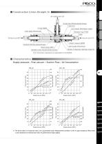
Guide ring (Nickel-plated brass) Tube End O-ring (NBR) Lock-claws (Stainless steel) Release ring (POM) Tube Exhaust port(EX) Joint body (Aluminum) Nozzle A (Special stainless steel ※) Metallic body (Nickel-plated brass) VACUUM ACCESSORIES Nozzle B (Nickel-plated brass) Joint body (Aluminum) VACUUM EXTERNAL VACUUM GENERATOR CONTROLLER ■ Construction (Union Straight A) ※ 2. Corrosion resistance is equivalent to SUS303. ■ Characteristics Supply pressure - Final vacuum / Suction Flow / Air Consumption VRL 100 n ptio 400 sum on ir c A 300 Suction flow 200 Flow rate (l/min(ANR)) Flow rate...
Open the catalog to page 3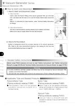
Vacuum Generator Series VACUUM GENERATOR Vacuum Generator VRL ■ How to insert and disconnect 1. How to insert and disconnect tubes ① Tube insertion Insert a tube into Push-In Fitting of the vacuum generator VRL up to the tube end. Lock-claws bite the tube to fix it and the elastic sleeve seals around the tube. Refer to “2. Instructions for Tube Insertion” under “Common Safety Instructions for Fittings” . ② Tube disconnection The tube is disconnected by pushing release-ring to release Lock-claws. Make sure to stop air supply before the tube disconnection. 2. How to fix the product Tighten a...
Open the catalog to page 4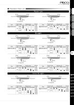
VACUUM EXTERNAL VACUUM GENERATOR CONTROLLER ■ Standard Size List Nipple type Thread Vacuum port Vacuum port Exhaust port Exhaust port Thread Page Air supply to refer port R1/8 R1/8 ● VRL Nipple type B 101 R1/4 Type Straight Fitting Vacuum port Thread Exhaust port Exhaust port Fitting Page Air supply Vacuum port Exhaust to refer port 6mm 8mm 10mm 12mm 16mm port ● R1/8 6mm ● VRL Straight A ● R1/8 ● 8mm R1/4 ● 102 R1/4 ● ● 10mm ● ● R1/2 Type Vacuum port VACUUM ACCESSORIES Page Air supply to refer port R1/8 6mm ● VRL Nipple type A ● 101 8mm Type Page Air supply to refer port R1/8 6mm ● VRL...
Open the catalog to page 5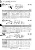
Vacuum Generator Series VRL Nipple type A Model code VACUUM GENERATOR Hex. Hex. Min. dia. of Final Suction Air Weight CAD flow channel vacuum flow consumption L2 øP1 øP2 C H1 H2 (ømm) (-kPa) (l/min(ANR)) (l/min(ANR)) (g) file name 31.6 12.4 30.6 14.4 ※ “L1” and “L2” are reference dimensions after tightening thread. ※ “L1” , “L2” , “L3” and “L4” are referential dimensions after tightening thread. Model code Min. dia. of Final Suction Air Weight CAD Hex. Hex. L1 L2 L3 L4 E1 E2 □ F flow channel vacuum flow consumption H1 H2 (ømm) (-kPa) (l/min(ANR)) (l/min(ANR)) (g) file name Model code...
Open the catalog to page 6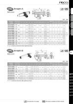
Unit:mm 対辺 Min. dia. of Final Suction Air Weight CAD flow channel vacuum flow consumption L2 øP1 øP2 øP3 C1 C2 H (ømm) (-kPa) (l/min(ANR)) (l/min(ANR)) (g) file name 31.6 VACUUM ACCESSORIES Model code VACUUM EXTERNAL VACUUM GENERATOR CONTROLLER ※ “L2” is reference dimensions after tightening thread. Unit:mm 対辺 Min. dia. of Final Suction Air Weight CAD flow channel vacuum flow consumption L2 øP1 øP2 øP3 C1 C2 H (ømm) (-kPa) (l/min(ANR)) (l/min(ANR)) (g) file name Model code ※ “L1” is reference dimension after tightening thread. Chart Characteristic chart page
Open the catalog to page 7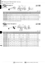
Vacuum Generator Series VRL Straight D compliant VACUUM GENERATOR Min. dia. of Final Suction Air Weight CAD 対辺 øP □ F flow channel vacuum flow consumption H1 (ømm) (-kPa) (l/min(ANR)) (l/min(ANR)) (g) file name ※ “L2” and “L3” are reference dimension after tightening thread. Min. dia. of Final Suction Air Weight CAD E2 flow channel vacuum flow consumption (ømm) (-kPa) (l/min(ANR)) (l/min(ANR)) (g) file name Chart Characteristic chart page
Open the catalog to page 8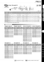
Model code Min. dia. of Final Suction Air Weight CAD E2 □ F flow channel vacuum flow consumption (ømm) (-kPa) (l/min(ANR)) (l/min(ANR)) (g) file name 56.9 16 VACUUM ACCESSORIES VACUUM EXTERNAL VACUUM GENERATOR CONTROLLER ※ “L2” is reference dimension after tightening thread. Model code Model code Model code Model code Model code Model code Model code Model code Union Straight A Union Straight B Chart Characteristic chart page CAD CAD data is available at PISC
Open the catalog to page 9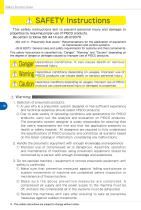
Safety Instructions SAFETY Instructions This safety instructions aim to prevent personal injury and damage to properties by requiring proper use of PISCO products. Be certain to follow ISO 4414 and JIS B 8370 ISO 4414Pneumatic fluid power…Recomendations for the application of equipment to transmission and control systems. JIS B 8370General rules and safety requirements for systems and their components. This safety instructions is classified into “Danger”, “Warning” and “Caution” depending on the degree of danger or damages caused by improper use of PISCO products. Danger Hazardous...
Open the catalog to page 10
http://www.pisco.co.jp http://www.pisco.co.jp Disclaimer 1. PISCO does not take any responsibility for any incidental or indirect loss, such as production line stop, interruption of business, loss of benefits, personal injury, etc., caused by any failure on use or application of PISCO products. 2. PISCO does not take any responsibility for any loss caused by natural disasters, fires not related to PISCO products, acts by third parties, and intentional or accidental damages of PISCO products due to incorrect usage. 3. PISCO does not take any responsibility for any loss caused by improper...
Open the catalog to page 11All NIHON PISCO CO. catalogs and technical brochures
-
CTB series
1 Pages
-
FUS8 series
3 Pages
-
31 & 32 Series
20 Pages
-
Vacuum Pad Soft Series
86 Pages
-
VP series
106 Pages
-
CHA series
8 Pages
-
Gripper Series
15 Pages
-
SVB Series
50 Pages
-
SVA series
13 Pages
-
SVR series
31 Pages
-
NSB series
8 Pages
-
Ball Valve SUS304 series
8 Pages
-
BV series
8 Pages
-
HV series
5 Pages
-
Cable clamp & Dividing sheet
8 Pages
-
Plarailchain SC
15 Pages
-
Plarailchain SPO
12 Pages
-
Plarailchain SP
14 Pages
-
HPO
12 Pages
-
HPU
12 Pages
-
PJN series
15 Pages
-
KJNC series
15 Pages
-
SSJS series
6 Pages
-
Flow Control Valve PP Series
12 Pages
-
Stainless SUS316
13 Pages
-
UE series
12 Pages
-
FB series
1 Pages
-
CTA series
1 Pages
-
SFTN series
2 Pages
-
SET series
1 Pages
-
SFT series
14 Pages
-
ULF series
12 Pages
-
UCQ series
2 Pages
-
UQ series
12 Pages
-
NB series
12 Pages
-
NA series
12 Pages
-
UD series
12 Pages
-
UBS series
12 Pages
-
UBT series
12 Pages
-
UC series
1 Pages
-
UB series
12 Pages
-
AK/AS series
26 Pages
-
NK series
18 Pages
-
Brass Series
30 Pages
-
V-0 series
27 Pages
-
EG Series
27 Pages
-
PP Fitting series
12 Pages
-
PP Series
26 Pages
-
AP series
18 Pages
-
SL series
16 Pages
-
P-SUS series
33 Pages
-
NS series
24 Pages
-
SSP series
8 Pages
-
ATS series
6 Pages
-
Air Filter
20 Pages
-
Combination Unit Series
25 Pages
-
SFU series
9 Pages
-
JP series
15 Pages
-
ET series
11 Pages
-
EQ series
19 Pages
-
CVLU series
21 Pages
-
CV series
24 Pages
-
JN series
25 Pages
-
Speed Controller Constant Flow
15 Pages
-
JSD series
10 Pages
-
JS Low-Flow series
17 Pages
-
JSC series
13 Pages
-
JS series
30 Pages
-
Miniature Pressure Regulator
12 Pages
-
MA series
16 Pages
-
RH series
16 Pages
-
R series
16 Pages
-
PS series
16 Pages
-
L series
41 Pages
-
FUS20
7 Pages
-
Small Flow Sensor FUS8 Sries
3 Pages
-
GP series
13 Pages
-
VUS-32. SEU-32 Series
1 Pages
-
Small Pressure Sensor 11-series
24 Pages
-
VUS12 series
2 Pages
-
VUS21 series
14 Pages
-
VUS8-S series
22 Pages
-
JSD series
10 Pages
-
Orifice Fitting Series
6 Pages
-
JK series
10 Pages
-
RVFUP series
6 Pages
-
VLF series
16 Pages
-
VFL series
8 Pages
-
VF series
22 Pages
-
ECV series
8 Pages
-
VPLFC, VPLFD series
17 Pages
-
VPKE series
4 Pages
-
RPV06 Series
8 Pages
-
VZ Series
34 Pages
-
VX Series
42 Pages
-
VQ Series
4 Pages
-
VN Series
40 Pages
-
VK series
53 Pages
-
VJ Series
34 Pages
-
VG series
21 Pages
-
VRL series
17 Pages
-
VVV series
11 Pages
-
VLS series
4 Pages
-
VM | VC series
28 Pages
-
VY series
24 Pages
-
VB series
11 Pages
-
VH | VS series
28 Pages
-
VPHMP series
12 Pages
-
VYR series
5 Pages
-
HS series
13 Pages
-
HML series
14 Pages
-
VRG series
18 Pages
-
Dry Unit Series
33 Pages
-
Fiber Membrane Air Dryer
12 Pages
-
VLM series
12 Pages
-
VSPE series
5 Pages
-
VT series
21 Pages
-
PB series
13 Pages
-
JSG series
17 Pages
-
pararel
3 Pages
-
fitting
4 Pages
-
BJSU series
4 Pages
-
SC
15 Pages
-
SPO
12 Pages
-
SP
13 Pages
-
RPV pump
8 Pages
-
Pre-set
6 Pages
-
Stainless Steel Ball Valve
8 Pages
-
SUS316 Flow Control Valve
6 Pages
-
Flange
13 Pages
-
HML
14 Pages
-
End of Arm Vacuum Gripper
12 Pages
-
VYR
5 Pages
-
EOAT VRG | VMG series
18 Pages
-
VPLFC
17 Pages
-
SVB
172 Pages
-
SVR
39 Pages
-
8mm Sensor
22 Pages
-
Vacuum Filter
28 Pages
-
Fall Prevention
18 Pages
-
Vacuum Pen
21 Pages
-
Push-Rod Release
4 Pages
-
cylinder
22 Pages
-
FDAbellows
6 Pages
-
Oval
80 Pages
-
sponge
50 Pages
-
mark-free
34 Pages
-
flat
42 Pages
-
Ultrathin
34 Pages
-
packaging bag
13 Pages
-
multi-bellow
46 Pages
-
bellows pad
74 Pages
-
Skid proof pad
42 Pages
-
soft bellow pad
60 Pages
-
soft pad
66 Pages
-
VH VS VC VUM VU VY VB
336 Pages
-
VZ
34 Pages
-
VX
42 Pages
-
VVV
11 Pages
-
VQ
42 Pages
-
VN
40 Pages
-
VLS
4 Pages
-
VLM
12 Pages
-
VK
53 Pages
-
VJ
34 Pages
-
VG
21 Pages
-
Vacuum Tube
12 Pages
-
Twin Coiling
12 Pages
-
Tube Cutter
12 Pages
-
Polyurethane Tube
12 Pages
-
Nylon Tube Series
12 Pages
-
Multi-core Planar Tube
12 Pages
-
Low-Friction Polyurethane Tube
12 Pages
-
Insert Ring
12 Pages
-
Fluororesin (PFA) Tube
14 Pages
-
UL series
12 Pages
-
Anti-spatter Tube
12 Pages
-
Tube Fitting PP Series
26 Pages
-
Tube Fitting Mini Series
41 Pages
-
Tube Fitting Chemical Series
18 Pages
-
K series
30 Pages
-
Stop Fitting Series
16 Pages
-
Rotary Joint Series
16 Pages
-
Multi-Circuit Rotary Block
12 Pages
-
Minimal Fitting Series
20 Pages
-
Main Block Series
24 Pages
-
Light Coupling Series
24 Pages
-
High Rotary Joint Series
16 Pages
-
Connector Series
16 Pages
-
Color Cap
12 Pages
-
Brass Compression Fitting Series
18 Pages
-
2-Circuit Junction Block Series
16 Pages
-
Vacuum EOAT Kit HML
14 Pages
-
Vacduum gripper
18 Pages
-
Mounting Flange for EOAT.pdf
13 Pages
-
SSNC series
13 Pages
-
SJSC series
24 Pages
-
Speed Controller Series
32 Pages
-
Speed Controller PP Series
17 Pages
-
Speed Controller Low Flow
17 Pages
-
Speed Controller High Flow
13 Pages
-
Speed Controller Brass Series
15 Pages
-
KJSC series
17 Pages
-
Silencer Series
13 Pages
-
Quick Exhaust Valve Series
19 Pages
-
Pressure Gauge Series
13 Pages
-
Miniture quick-exhaust
17 Pages
-
Fixed Orifice Joint Series
22 Pages
-
Check Valve
4 Pages
-
SUS304_Ball Valve Series
8 Pages
-
Parallel Gripper
6 Pages
-
JSG
17 Pages
-
GENERAL
106 Pages
-
Mechanical Valve Series
19 Pages
-
Ball Valve Series
19 Pages
-
Stainless Steel ball valve
6 Pages
-
Hand Valve Series
15 Pages
-
Change Valve
11 Pages
-
SVA21 Series
21 Pages
-
P Series
71 Pages
-
SVA20 Series
43 Pages
-
RegulatorPL031821m
12 Pages
-
BJSU series
6 Pages
-
NP68-01e
17 Pages


