
- Catalogs
- NIHON PISCO CO., Ltd.
- FUS8 series

- Company
- Products
- Catalogs
- News & Trends
- Exhibitions
FUS8 series

FUS8 series
Overview
The document details the specifications, features, installation methods, model designations, safety instructions, and operating conditions for the Small Flow Sensor FUS8 series, designed primarily for suction lift verification in pneumatic systems.
Product Characteristics
- Ultra-small and lightweight sensor (8.5mm width, 24mm height, 41mm length, 10.7g with ø4mm push-in fitting).
- Multiple connection methods available: push-in fitting, barb fitting, stem type, and female thread model.
- Three installation methods: direct screw mounting, holder mounting, and sensor head direct mount for minimal space installation.
- Non-linear sensor type optimized for suction lift verification, including bidirectional flow measurement for suction lift and release verification.
- Best suited for detecting suction lift of small workpieces and applications where pressure sensors are ineffective due to long piping or narrow vacuum flow.
Model Designation and Options
The model code structure includes:
- Sensor type: FUS8 (non-linear flow sensor)
- Output type: Analog (1V to 5V)
- Flow direction: One-directional (F) or Bi-directional (R)
- Flow rate range: 0.5, 1, 5, or 10 l/min full scale
- Port sizes selectable for inside and outside ports (ø1.8mm to ø6×ø4mm)
- Cable options: with or without 3-core 3m cable
- Holder options: with or without holder (not selectable with sensor head unit)
Specifications
| Parameter | Value / Range |
|---|---|
| Fluid Medium | Clean air (JIS B8392-1), Nitrogen |
| Operating Pressure Range | -0.09 to 0.2 MPa (-26.58 to 59.06 in.Hg) |
| Proof Pressure | 0.3 MPa (-88.59 in.Hg) |
| Operating Ambient Temperature & Humidity | 0 to 50°C (32 to 122°F), Max 80% RH |
| Fluid Medium Temperature | 0 to 50°C (32 to 122°F), no dew condensation |
| Storage Temperature | -20 to 60°C (-4 to 140°F), no dew condensation |
| Output Accuracy | Non-linear analog output 1-5V |
| Pressure Characteristics | Max ±5% F.S (typical), Max ±10% F.S (worst case) |
| Temperature Characteristics | Max ±0.3% F.S (typical), Max ±0.6% F.S (worst case) |
| Repeatability | Max ±2% F.S |
| Power Supply Voltage | 24 VDC ±10% |
| Current Consumption | Max 30 mA |
| Response Time | Max 5 ms (one-directional), Max 8 ms (bi-directional) |
Note: Bi-directional type outputs 3V at zero flow; output varies from 1V to 5V depending on flow direction.
Installation and Connection Methods
- Direct screw mounting for fixed installation.
- Holder mounting for easy installation and removal.
- Sensor head direct mount for minimal space requirements.
- Connection options include push-in fittings (ø1.8 to ø4mm), barb fittings (ø6×ø4mm), stem types (ø4, ø6mm), and female thread (M5×0.8).
Applications
- Suction lift verification of small workpieces difficult to detect by pressure sensors.
- Verification in long piping systems where pressure detection is challenging.
- Applications requiring narrow vacuum flow to secure pressure difference and longer tact time for suction lift verification.
Safety and Usage Instructions
- Do not use in flammable or corrosive gas environments.
- Power must be off during wiring; use insulated, stabilized DC power supply within rated voltage.
- Use only for industrial purposes, not for commercial measurement.
- Install air filters upstream to prevent foreign material suction.
- Avoid dew condensation inside piping by controlling ambient and fluid temperatures.
- Prevent bending near tube fittings; use insert rings if necessary.
- Avoid excessive vibration or shock (>100 m/s²) to prevent output fluctuation or sensor detachment.
- Keep sensor and wiring away from strong electrical noise sources.
- Protect against counter-currents and surge currents to avoid damage.
- Do not apply repetitive bending or tensile force on lead wires.
- Avoid external mechanical stress on the sensor body and connectors during operation.
- Operating temperature range: 0°C to 50°C; avoid sudden temperature changes causing condensation.
- Do not operate outside specified pressure and flow ranges to prevent malfunction.
- Use only with clean, dry air or nitrogen free of chlorine, sulfur, acid, dust, and oil mist.
- Install filters, air dryers, and oil mist filters on the primary side to protect sensor internals.
- Use oil-free valves and filters to prevent abrasion powder contamination.
- Allow at least 5 minutes standby time after energizing before use for output stability.
- Perform periodic maintenance at least annually; expect output variation up to ±6% F.S (one-directional) or ±3% F.S (bi-directional) over time.
- Do not dismantle or modify the product.
- Clean sensor case with care; avoid solvents, alcohol, or detergents that may damage resin.
Model and Accessory Codes
Examples of model codes are provided for various flow ranges, flow directions, cable options, and holder presence. Accessories include holders and cables with specific codes.
Packaging
Each sensor is packaged individually in a bag.
Summary
The FUS8 series small flow sensors provide precise, compact, and versatile solutions for suction lift verification in pneumatic systems, especially where pressure sensors are inadequate. Multiple installation and connection options, combined with detailed safety and usage guidelines, ensure reliable operation in industrial environments.
Catalog excerpts
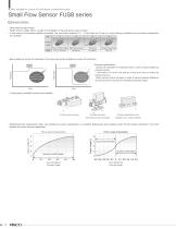
Best suitable for suction lift verification of small work piece Small Flow Sensor FUS8 series Characteristics • Ultra-small and light weight Width: 8.5mm, Height: 24mm, Length: 41mm,Weight: 10.7g (with ø4mm push-in fitting) • A wide variety of connection method is available. The connection methods of ① ~ ④ are lined up. On top of it, various fitting combination for connection configuration are available. No. ① ② ③ ④ Connection method size Barb fitting model ø6×ø4mm Female thread model M5×0.8 • Best suitable for suction lift verification. Non-linear type sensor suitable for suction lift verification. -Suction lift verification of small work piece, which is hard to detect by pressure sensor. -Verification for which the piping is long and hard to detect by pressure sensor. -When vacuum flow is narrowed in order to secure pressure difference and the tact time to suction lift verification becomes longer. Suction Flow rate Hard to detect by small pressure gap. Clear detection is possible by flow rate gap. • Three types of installation method are available. ① Direct screw mounting ③ Sensor head direct mount -Easy installation and removal of the product -Installation on min. space is possible. • Bidirectional flow measurement type, best suitable for suction transportation, is available. Bidirectional type enables suction lift and release verification. Thus, best suitable for suction transport application. Flow to output characteristics Flow to output characteristics 5 Suction confirmation Flow rate (ℓ/min) One-way model Vacuum break confirmation. Suction confirmation
Open the catalog to page 1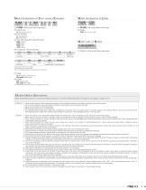
Model designation of Flow sensor (Example) FUS8 (1) Model designation of Cable FUS8 (1) FUS8: Flow sensor (Non-linear type) (2) Output type (1) FUS8: Flow sensor (Non-linear type) (2) Cable (4) Flow rate range (Full scale flow rate) Model code of Holder (5) In-side port (6) Out-side port Code (1) Holder for flow sensor (Non-linear type) Push-in fitting Barb fitting female thread sensor head unit *Flow rate of ø1.8mm is max. 4l/min. *Flow rate of ø2 mm is max. 5l/min. *Size of In-side/Out-side port is selectable from the above list. (7) Cable 3: With cable (3 cores and 3 m) No code: Without cable...
Open the catalog to page 2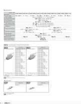
Operating conditions Model code FUS8-A-R005 FUS8-A-R010 FUS8-A-R050 FUS8-A-R100 FUS8-A-F005 FUS8-A-F010 FUS8-A-F050 FUS8-A-F100 Description Flow rate range -0.5 ~ 0.5l/min -1 ~ 1l/min -5 ~ 5l/min -10 ~ 10l/min 0 ~ 0.5l/min 0 ~ 1l/min 0 ~ 5l/min 0 ~ 10l/min Fluid medium Clean air (JIS B8392-1, 1.1.1~1.6.2), Nitrogen Operating pressure range -0.09 ~ 0.2MPa (-26.58 ~ 59.06in.Hg) Proof pressure 0.3MPa (-88.59in.Hg) Operating ambient temp. & hum. 32 ~ 122°F (0 ~ 50°C) Max.80%RH Fluid medium temp. 32 ~ 122°F (0 ~ 50°C) (No dew condensation) Temperature range at storing -4 ~ 140°F (-20 ~60°C) (No dew...
Open the catalog to page 3All NIHON PISCO CO., Ltd. catalogs and technical brochures
 Vacuum Pad Holder Resin Body
9 Pages
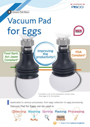 Vacuum Pad for Eggs
6 Pages
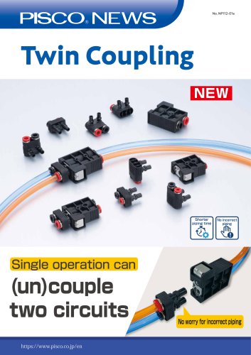 Twin Coupling
6 Pages
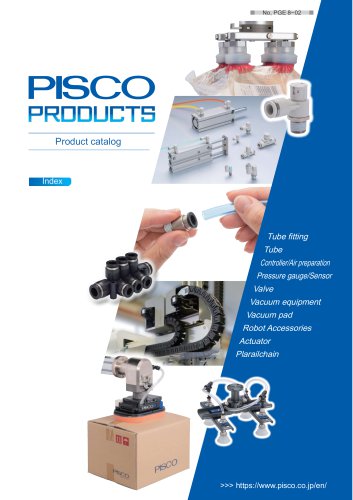 General Product Guide
917 Pages
 CTB series
1 Page
 31 & 32 Series
20 Pages
 Vacuum Pad Soft Series
86 Pages
 VP series
106 Pages
 CHA series
8 Pages
 Gripper Series
15 Pages
 SVB Series
50 Pages
 SVA series
13 Pages
 SVR series
31 Pages
 NSB series
8 Pages
 Ball Valve SUS304 series
8 Pages
 BV series
8 Pages
 HV series
5 Pages
 Cable clamp & Dividing sheet
8 Pages
 Plarailchain SC
15 Pages
 Plarailchain SPO
12 Pages
 Plarailchain SP
14 Pages
 HPO
HPO12 Pages
 HPU
HPU12 Pages
 PJN series
15 Pages
 KJNC series
15 Pages
 SSJS series
6 Pages
 Flow Control Valve PP Series
12 Pages
 Stainless SUS316
13 Pages
 UE series
12 Pages
 FB series
1 Page
 CTA series
1 Page
 SFTN series
2 Pages
 SET series
1 Page
 SFT series
14 Pages
 ULF series
12 Pages
 UCQ series
2 Pages
 UQ series
12 Pages
 NB series
12 Pages
 NA series
12 Pages
 UD series
12 Pages
 UBS series
12 Pages
 UBT series
12 Pages
 UC series
1 Page
 UB series
12 Pages
 AK/AS series
26 Pages
 NK series
18 Pages
 Brass Series
30 Pages
 V-0 series
27 Pages
 EG Series
27 Pages
 PP Fitting series
12 Pages
 PP Series
26 Pages
 AP series
18 Pages
 SL series
16 Pages
 P-SUS series
33 Pages
 NS series
24 Pages
 SSP series
8 Pages
 ATS series
6 Pages
 Air Filter
20 Pages
 Combination Unit Series
25 Pages
 SFU series
9 Pages
 JP series
15 Pages
 ET series
11 Pages
 EQ series
19 Pages
 CVLU series
21 Pages
 CV series
24 Pages
 JN series
25 Pages
 Speed Controller Constant Flow
15 Pages
 JSD series
10 Pages
 JS Low-Flow series
17 Pages
 JSC series
13 Pages
 JS series
30 Pages
 Miniature Pressure Regulator
12 Pages
 MA series
16 Pages
 RH series
16 Pages
 R series
16 Pages
 PS series
16 Pages
 L series
41 Pages
 FUS20
FUS207 Pages
 Small Flow Sensor FUS8 Sries
3 Pages
 GP series
13 Pages
 VUS-32. SEU-32 Series
1 Page
 Small Pressure Sensor 11-series
24 Pages
 VUS12 series
2 Pages
 VUS21 series
14 Pages
 VUS8-S series
22 Pages
 JSD series
10 Pages
 Orifice Fitting Series
6 Pages
 JK series
10 Pages
 RVFUP series
6 Pages
 VLF series
16 Pages
 VFL series
8 Pages
 VF series
22 Pages
 ECV series
8 Pages
 VPLFC, VPLFD series
17 Pages
 VPKE series
4 Pages
 RPV06 Series
8 Pages
 VZ Series
34 Pages
 VX Series
42 Pages
 VQ Series
4 Pages
 VN Series
40 Pages
 VK series
53 Pages
 VJ Series
34 Pages
 VG series
21 Pages
 VRL series
17 Pages
 VVV series
11 Pages
 VLS series
4 Pages
 VM | VC series
28 Pages
 VY series
24 Pages
 VB series
11 Pages
 VH | VS series
28 Pages
 VPHMP series
12 Pages
 VYR series
5 Pages
 HS series
13 Pages
 HML series
14 Pages
 VRG series
18 Pages
 Dry Unit Series
33 Pages
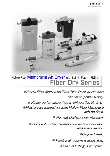 Fiber Membrane Air Dryer
12 Pages
 VLM series
12 Pages
 VSPE series
5 Pages
 VT series
21 Pages
 PB series
13 Pages
 JSG series
17 Pages
 pararel
3 Pages
 fitting
4 Pages
 BJSU series
4 Pages
 SC
SC15 Pages
 SPO
SPO12 Pages
 SP
SP13 Pages
 RPV pump
8 Pages
 Pre-set
6 Pages
 Stainless Steel Ball Valve
8 Pages
 SUS316 Flow Control Valve
6 Pages
 Flange
13 Pages
 HML
HML14 Pages
 End of Arm Vacuum Gripper
12 Pages
 VYR
VYR5 Pages
 EOAT VRG | VMG series
18 Pages
 VPLFC
VPLFC17 Pages
 SVB
SVB172 Pages
 SVR
SVR39 Pages
 8mm Sensor
22 Pages
 Vacuum Filter
28 Pages
 Fall Prevention
18 Pages
 Vacuum Pen
21 Pages
 Push-Rod Release
4 Pages
 cylinder
22 Pages
 FDAbellows
6 Pages
 Oval
Oval80 Pages
 sponge
50 Pages
 mark-free
34 Pages
 flat
flat42 Pages
 Ultrathin
34 Pages
 packaging bag
13 Pages
 multi-bellow
46 Pages
 bellows pad
74 Pages
 Skid proof pad
42 Pages
 soft bellow pad
60 Pages
 soft pad
66 Pages
 VRL
VRL17 Pages
 VH VS VC VUM VU VY VB
336 Pages
 VZ
VZ34 Pages
 VX
VX42 Pages
 VVV
VVV11 Pages
 VQ
VQ42 Pages
 VN
VN40 Pages
 VLS
VLS4 Pages
 VLM
VLM12 Pages
 VK
VK53 Pages
 VJ
VJ34 Pages
 VG
VG21 Pages
 Vacuum Tube
12 Pages
 Twin Coiling
12 Pages
 Tube Cutter
12 Pages
 Polyurethane Tube
12 Pages
 Nylon Tube Series
12 Pages
 Multi-core Planar Tube
12 Pages
 Low-Friction Polyurethane Tube
12 Pages
 Insert Ring
12 Pages
 Fluororesin (PFA) Tube
14 Pages
 UL series
12 Pages
 Anti-spatter Tube
12 Pages
 Tube Fitting PP Series
26 Pages
 Tube Fitting Mini Series
41 Pages
 Tube Fitting Chemical Series
18 Pages
 K series
30 Pages
 Stop Fitting Series
16 Pages
 Rotary Joint Series
16 Pages
 Multi-Circuit Rotary Block
12 Pages
 Minimal Fitting Series
20 Pages
 Main Block Series
24 Pages
 Light Coupling Series
24 Pages
 High Rotary Joint Series
16 Pages
 Connector Series
16 Pages
 Color Cap
12 Pages
 Brass Compression Fitting Series
18 Pages
 2-Circuit Junction Block Series
16 Pages
 Vacuum EOAT Kit HML
14 Pages
 Vacduum gripper
18 Pages
 Mounting Flange for EOAT.pdf
13 Pages
 SSNC series
13 Pages
 SJSC series
24 Pages
 Speed Controller Series
32 Pages
 Speed Controller PP Series
17 Pages
 Speed Controller Low Flow
17 Pages
 Speed Controller High Flow
13 Pages
 Speed Controller Brass Series
15 Pages
 KJSC series
17 Pages
 Silencer Series
13 Pages
 Quick Exhaust Valve Series
19 Pages
 Pressure Gauge Series
13 Pages
 Miniture quick-exhaust
17 Pages
 Fixed Orifice Joint Series
22 Pages
 Check Valve
4 Pages
 SUS304_Ball Valve Series
8 Pages
 Parallel Gripper
6 Pages
 JSG
JSG17 Pages
 GENERAL
106 Pages
 Mechanical Valve Series
19 Pages
 Ball Valve Series
19 Pages
 Stainless Steel ball valve
6 Pages
 Hand Valve Series
15 Pages
 Change Valve
11 Pages
 SVA21 Series
21 Pages
 P Series
71 Pages
 SVA20 Series
43 Pages
 RegulatorPL031821m
12 Pages
 BJSU series
6 Pages
 NP68-01e
17 Pages


- NIHON PISCO manual valve
- Control valve
- NIHON PISCO stainless steel valve
- NIHON PISCO hydraulic fitting
- Vessel
- Water valve
- Ball valve
- Screw-in fitting
- NIHON PISCO pneumatic valve
- NIHON PISCO pneumatic fitting
- Electrically operated valve
- NIHON PISCO threaded valve
- NIHON PISCO vacuum generator
- NIHON PISCO metal fitting
- Regulating valve
- On/off valve
- Vacuum pump