Catalog excerpts

SCREW SUPPORTS
Open the catalog to page 1
“IF YOU WANT A creative team, GIVE THEM ENOUGH TIME TO PLAY.” JOHN CLEESE MEMBER OF MONTY PYTHON.
Open the catalog to page 3
SCREW SUPPORTS INTRODUCTION NIASA SH Series screw supports are a simple and economical solution for mounting a screw on a support and fastening it to any part of a machine. The turn of the screw moves its corresponding nut and with this the desired part of the machine moves (carriages, tables, etc.). They are also also characterized for offering an extensive range of: …… Axial load capacities, from 2.5 kN up to 45 kN. …… Nut advance speeds depend on the screw pitch and the transmission used. The screw supports are motorized in a very simple way, by motors or motoreducers in different...
Open the catalog to page 5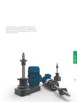
Please do not hesitate to contact NIASA if you require screw supports (and their drive mechanisms) with specifications other than those covered in this chapter. The NIASA technical department will specifically develop the special units that best meet your requirements.
Open the catalog to page 6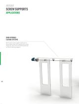
SCREW SUPPORTS APPLICATIONS Door opening/ closing systems SH20 Series screw support made up of a three-phase motor drive system, drive union flange, left-right screw with KGF double ball nut and SP bearing supports.
Open the catalog to page 7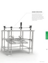
Machine TILTING system Set of four SH30 Series screw supports made up of a servomotor drive system and joined together with GX transmission shaft and bevel gearboxes. Screw fastening with BPS flanges, KGF ball nuts, SF Series spiral screw protectors and two electromagnetic brakes.
Open the catalog to page 8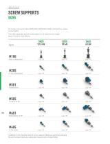
SCREW SUPPORTS For further information about M205/M501/M505/M601/M605 configurations, please contact NIASA. There are trapezoidal and ball screw options on all sizes (see the chapter about screws for more details). Basic configuration page 186 page 187 page 188 In line motoreducer page 185 page 185 page 185 Parallel drive page 185 page 185 page 185 For drive at 90° page 185 page 185 page 185 Motoreducer at 90° page 185 page 185 page 185 In line motor page 185 page 185 page 185 In addition to the standard range of screw supports, NIASA can specifically develop the unit that best meets your...
Open the catalog to page 9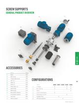
SCREW SUPPORTS GENERAL PRODUCT OVERVIEW Name Page
Open the catalog to page 10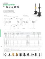
The capacities indicated correspond to the standard input shaft configurations. Higher capacities are available on request. NOTES: (1) See nut dimensions in the corresponding chapter. Screw diameter and step (mm) Maximum axial strength (kN) Advance (mm/revol. input) Drive torque, MD (Nm) F (kN), load to move in dynamic Stroke weight 0 without nut (kg) Approx. weight each 100 mm of stroke without nut (kg) … Power required: PD (kW) = 0,157x MD (Nm). … Contact NIASA to ensure the dynamic load does not exceed the critical values indicated, in order to avoid buckling and resonance of the unit....
Open the catalog to page 11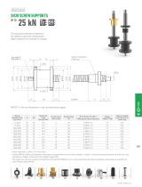
The capacities indicated correspond to the standard input shaft configurations. Higher capacities are available on request. NOTES: (1) See nut dimensions in the corresponding chapter. Screw diameter and step (mm) Maximum axial strength (kN) Travel (mm/ revol. input) Drive torque, MD (Nm) F (kN), load to move in dynamic Approx. weight each 100 mm of stroke (kg) … Power required: PD (kW) = 0,157x MD (Nm). … Contact NIASA to ensure the dynamic load does not exceed the critical values indicated, in order to avoid buckling and resonance of the unit. See calculations chapter at the end of the...
Open the catalog to page 12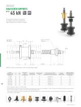
The capacities indicated correspond to the standard input shaft configurations. Higher capacities are available on request. NOTES: (1) See nut dimensions in the corresponding chapter. Screw diameter and step (mm) Maximum axial strength (kN) Travel (mm/ revol. input) Drive torque, MD (Nm) F (kN), load to move in dynamic Approx. weight each 100 mm of stroke (kg) … Power required: PD (kW) = 0,157x MD (Nm). … Contact NIASA to ensure the dynamic load does not exceed the critical values indicated, in order to avoid over-heating, buckling and resonance of the unit. See calculations chapter at the...
Open the catalog to page 13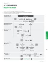
SCREW SUPPORTS Product selection To select the correct screw support, please follow this flow diagram. If you would like to know the expected service life of a unit for your application, please send the relevant data to the NIASA service department. SCREW SUPPORT MODEL 1 AND SIZE DEFINITION APPLICATION M100 BASE CONFIGURATION OTHER CONFIGURATION Page 184 SIZE PRE-SELECTION SCREW AND ADVANCE 2 DEFINITION OFSPEED TYPE SCREW TYPE Ball (KGS) Trapezoidal (Tr) SPECIAL 3 SCREW SUPPORT SIZE VALIDATION Only for load Page with compression 191 DRIVE TORQUE 4 CALCULATION AND POWER LATERAL LOADS SCREW...
Open the catalog to page 14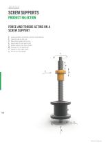
SCREW SUPPORTS Product selection FORCE AND TORQUE ACTING ON A SCREW SUPPORT F Load elevation at traction and/or compression. FL Lateral load on the nut. V Movement speed of the nut. FA Axial load on the input shaft. FR Radial load on the input shaft. MD Torque on the input shaft. n Speed on the input shaft. ns Screw turning speed.
Open the catalog to page 15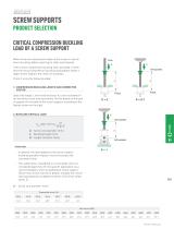
SCREW SUPPORTS Product selection CRITICAL COMPRESSION BUCKLING LOAD OF A SCREW SUPPORT When there are compression loads on the screw, it may fail due to buckling, before reaching its static load capacity. If the critical compression buckling load calculated is lower than the actual compression buckling load applied, select a larger screw support and check its suitability. Check it using the following steps: 1. Compression buckling length and corrector factor Select the length L (mm) and the factor K, to be considered in the buckling critical load calculation. Do this based on the type of...
Open the catalog to page 16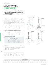
SCREW SUPPORTS Product selection CRITICAL RESONANCE SPEED OF A screw support Free With reduced diameter and long length screws, there is a risk that there will be considerable vibration on turning if this occurs at speeds close to the first vibration frequency (the second and highest correspond to very high speeds, at which the screws never work). In the worst cases, the screw may break and, additionally, the risk of collapse due to side buckling considerably increases. For these reasons, it must be checked that the screw support works at lower rotation speeds than resonance speeds. If not,...
Open the catalog to page 17All NIASA catalogs and technical brochures
-
Bevel Gearboxes
24 Pages
-
Screw Jacks
50 Pages
-
Ball Screw Drives
36 Pages
-
LINEAR TABLES
19 Pages
-
RODLESS MECHANICAL CYLINDERS
16 Pages


