
- Catalogs
- NIASA, NEFF Y ASOCIADOS, S.A.
- Electromechanical linear actuators


Electromechanical linear actuators
Electromechanical linear actuators
NIASA F/A Series linear actuators are electro-mechanical devices designed for precise linear movement, suitable for harsh environments due to their high sealing. They consist of a round stem within a steel or aluminum tube, driven by an electric motor and screw/nut mechanism.
These actuators offer high precision, energy efficiency, and reliability, supporting axial loads from 3.5 kN to 86 kN. They feature various screw types and materials, with options for anti-rotation and magnetic sensors. The outer tube can be steel or aluminum.
Applications include shutter systems, drive systems, scissor lifts, and antenna orientation systems, each utilizing specific configurations and accessories for optimal performance.
The F Series uses steel tubes, while the A Series uses aluminum tubes, offering trapezoidal and ball screw options. Configurations include in-line motoreducers, parallel drives, and 90º drives, with models like M205, M501, and M505.
Accessories such as tilt supports, flanges, clevis rods, limit switches, and sensors enhance actuator adaptability and functionality.
NIASA provides custom solutions tailored to specific actuator requirements beyond standard offerings.
Options for alternating or stepper motors are available, with recommendations for motors with brakes to prevent position loss. Standard brakes are typically sufficient for most motor sizes.
Various configurations (M501, M505, M601, M605) are detailed, highlighting coaxial motoreducers and pulley ratio modifications for desired transmission ratios.
Tables specify screw diameters, pitches, and load capacities for different models (F16 to F50), including maximum axial strength and motor power requirements.
Standard drives use AC motors with aluminum pulleys and polyurethane toothed straps, detailing power availability and motor flange types.
Guidelines for calculating drive torque and power requirements emphasize safety coefficients and start-up torque calculations.
Lubrication intervals depend on work type and cycle, with recommendations for automatic lubrication systems and specific grease types. A complete cleaning and grease change is recommended every five years.
Appropriate corrosion protection should be selected based on environmental conditions, following DIN EN ISO 12944-2 standards. NIASA should be contacted for higher corrosion resistance needs.
- C3: Medium urban and industrial atmospheres with moderate SO2 pollution.
- C4: High industrial and coastal areas with moderate salinity.
- C5-I: Very high industrial areas with high humidity.
- C5-M: Very high maritime areas with high salinity.
- Low (L): 2 to 5 years
- Medium (M): 5 to 15 years
- High (H): More than 15 years
NIASA actuators offer an IP65 protection index as standard, with higher levels available upon request, defined by DIN EN IEC 60529.
For environments below -20ºC or above +40ºC, contact NIASA for suitable materials and sealing components.
Optional configurations include immobilizations, special configurations for higher speeds, and various mounting and drive adaptations.
Includes size, configuration, reduction, screw type, stroke, immobilization, and accessories.
Detailed parts list for F and A series actuators, including body, caps, screws, nuts, bearings, seals, and more.
Custom modifications are available for specific requirements, including special flanges, trunnion mounts, and compact units.
Catalog excerpts
LINEAR ACTUATORS F series: Steel tube A series: Aluminum tube
Open the catalog to page 1
“WE ARE WHAT WE REPEATEDLY DO. EXCELLENCE, THEN, IS NOT AN ACT, BUT A HABIT.” ARISTOTLE Philosophy
Open the catalog to page 3
LINEARtube | A SERIES: aluminum tube ACTUATORS F SERIES: steel INTRODUCTION NIASA F/A Series linear actuators are electro-mechanical cylinders in which a round stem moves inside a second tube, of either steel or aluminum. The lengthwise movement of the stem is achieved with the combination of an interior screw/nut which drags it, and an electrical motor that drives the screw/nut. The power transmission from the motor may be direct or by means of different gear solutions and toothed belts. Against solutions with exposed screws, protecting them with an external stem means that the equipment is...
Open the catalog to page 5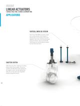
LINEARtube | A SERIES: aluminum tube ACTUATORS F SERIES: steel Applications Vertical drive DE system Set of two F30-M505 actuators made up of a servomotor drive system, a special drive union flange and joined together with a GX universal joint shaft. Inductive sensor, clevis rod with GIR Series ball joint and protection bellow for the FB Series stem. SHUTTER SYSTEM A30 Series actuator made up of a threephase motor drive system, tilt on the outside with BA Series bolts, SB Series tilt support, clevis rod with GIR Series ball joint on the stem and integrated position magnetic sensor.
Open the catalog to page 7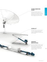
Antenna orientation system A40 Series actuator made up of a servomotor drive system, drive union flange, tilt on the outside with BA Series bolts, SB Series tilt support and GK Series single clevis rod on the stem. Scissor lift F45–M501 made up of a three-phase motor drive system, SB Series tilt supports and GKB Series double clevis rod on the stem. Horizontal drive DE system Set of two F30-M205 actuators, made up of a drive system of a three-phase line motoreducer, independently commanded and fastened with SB Series tilt supports and BP Series plates on the stem.
Open the catalog to page 8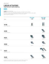
LINEARtube | A SERIES: aluminum tube ACTUATORS F SERIES: steel SIZES F SERIES: Steel outside tube. SERIES A: Aluminum outside tube (stem anti-rotation and magnetic sensor optional). For further information about M205/M501/M505/M605 A Series configurations, please contact NIASA. There are trapezoidal and ball screw options on all sizes (see chapter 07 about screws for more details). Basic configuration Parallel drive In line motor In addition to the standard range of F/A Series linear actuators, NIASA can specifically develop the unit that best meets your application requirements. Contact NIASA....
Open the catalog to page 9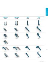
page 82 page 84 page 86 page 87 page 88 page 88 page 88 page 88 page 90 page 90 page 90 page 90 page 93 page 93 page 93 page 93 page 94 page 94 page 94 page 94
Open the catalog to page 10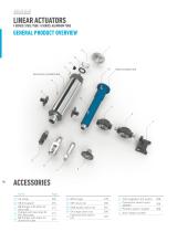
LINEARtube | A SERIES: aluminum tube ACTUATORS F SERIES: steel General product overview 14 Steel outside tube Aluminum outside tube 11 ACCESSORIES Name 02 SB tilt support 03 BB flanges with bolts for steel tube Flanges with bearings for 04 BH steel tube with 05 BB flangestube bolts for aluminum 09 GK single clevis rod 10 Inductive limit switch FCI 11 FCG magnetic limit switch 12 Connection sensor input adapter 13 Position sensor magnet 14 Anti-rotation system
Open the catalog to page 11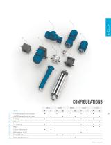
Name FAFAFAFAFA 01 F-M100 series linear actuator • • • • • 02 A-M100 series linear actuator • • • • •
Open the catalog to page 12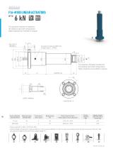
The capacities indicated correspond to the standard input shaft configurations. Higher capacities are available on request. Greasing mechanism DIN71412 Straight type A - MT503 The capacities indicated correspond to the standard input shaft configurations. Higher capacities are available on request. 15 36 SAFETY MARGIN CHECKED BY -A- Screw diameter and step (mm) Maximum axial strength (kN) Travel (mm/ revol. input) Drive torque, MD (Nm) F (kN), load to move in dynamic Approx. weight each 100 mm of Stroke (kg) … Power required: PD (kW) = 0,157x MD (Nm). … Contact NIASA if the dynamic load exceeds...
Open the catalog to page 13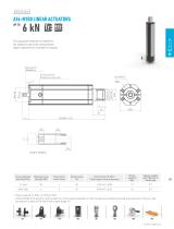
The capacities indicated correspond to the standard input shaft configurations. Higher capacities are available on request. Screw and nut greasing access cap Screw and nut greasing access cap 35 SAFETY MARGIN 35 SAFETY MARGIN Screw diameter and step (mm) Maximum axial strength (kN) Travel (mm/ revol. input) Drive torque, MD (Nm) F (kN), load to move in dynamic Approx. weight each 100 mm of Stroke (kg) … Power required: PD (kW) = 0,157x MD (Nm). … Contact NIASA if the dynamic load exceeds the critical values indicated, in order to avoid over-heating, buckling and resonance of the unit. See calculations...
Open the catalog to page 14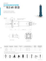
The capacities indicated correspond to the standard input shaft configurations. Higher capacities are available on request. Greasing mechanism DIN71412 Straight type A - MT503 26 36 SAFETY MARGIN CHECKED BY -A- Screw diameter and step (mm) Maximum axial strength (kN) Travel (mm/ revol. input) Drive torque, MD (Nm) F (kN), load to move in dynamic Approx. weight each 100 mm of Stroke (kg) … Power required: PD (kW) = 0,157x MD (Nm). … Contact NIASA if the dynamic load exceeds the critical values indicated, in order to avoid over-heating, buckling and resonance of the unit. See calculations chapter...
Open the catalog to page 15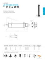
The capacities indicated correspond to the standard input shaft configurations. Higher capacities are available on request. Key 5x5x20 DIN6885-A Key 5x5x20 DIN6885-A 4 A Screw and nut greasing access cap Screw and nut greasing access cap 35 SAFETY MARGIN 35 SAFETY MARGIN Screw diameter and step (mm) Maximum axial strength (kN) Travel (mm/ revol. input) Drive torque, MD (Nm) F (kN), load to move in dynamic Approx. weight each 100 mm of Stroke (kg) … Power required: PD (kW) = 0,157x MD (Nm). … Contact NIASA if the dynamic load exceeds the critical values indicated, in order to avoid over-heating,...
Open the catalog to page 16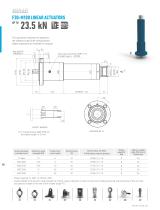
The capacities indicated correspond to the standard input shaft configurations. Higher capacities are available on request. 3 Greasing mechanism DIN71412 Straight type A - MT503 30 37 SAFETY MARGIN CHECKED BY -A- (*) If incorporating a KGM 3220 nut, the safety margin is 15 mm. Screw diameter and step (mm) Maximum axial strength (kN) Travel (mm/ revol. input) Drive torque, MD (Nm) F (kN), load to move in dynamic Approx. weight each 100 mm of Stroke (kg) … Power required: PD (kW) = 0,157x MD (Nm). … Contact NIASA if the dynamic load exceeds the critical values indicated, in order to avoid over-heating,...
Open the catalog to page 17All NIASA, NEFF Y ASOCIADOS, S.A. catalogs and technical brochures
 Screw Supports
24 Pages
 Ball Screw Drives
36 Pages
 Bevel Gearboxes
24 Pages
 Screw Jacks
50 Pages
 LINEAR TABLES
19 Pages
 RODLESS MECHANICAL CYLINDERS
16 Pages
- Electric actuator
- Positioning table
- Translation stage
- Screw actuator
- Single-axis positioning stage
- Electric cylinder
- Extruded aluminum actuator
- Screw jack
- Translating screw jack
- Rotating screw jack
- Trapezoidal screw jack
- Ball screw jack
- Slide actuator
- Safety nut screw jack
- Rodless actuator
- Rodless cylinder
- Custom-made stage